Sunday, November 30, 2008

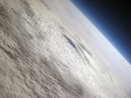
Link: High altitude still pictures (60000 ft up)


jcoxon77's photostream, Flicr:
http://www.flickr.com/photos/jcoxon77/

They look pretty cool, don't they?

But 76500 ft looks even cooler:


http://www.flickr.com/photos/nebarnix/sets/72157607393699828/

Interestingly though, 42000 ft still looks pretty amazing:

Will it blend?


Seems like, yes it did :)


Created with the latest iRhino alpha.

Changes:
* Placeholder engine nacelles added.
* Rudder added

I was reading today the book "Fluid dynamic drag" a bit and got kind of inspired: canopies and wind shield discontinuity contributes very much to the drag coefficient of the fuselage. Not only the laminar nose seems important, but all kinds of places where something ends and something else continues are sources of waste of engery.

So if the plane is completely faired with no discontinuity of any kind, theoretically the drag coefficient should be very low.
In this picture, the engine nacelle placeholders are just placeholders, because they are not yet accurate airfoil, and it has not been taken into account that in Rotax engines the propeller shaft is not in the middle of the engine, but almost on the top of the engine, this creates a fairing that has the lower side turned up a bit and is therefore not completely symmetrical.

The engine nacelles may need to be moved outwards, otherwise there is not enough clearance between the fuselage and the propeller arc.

I was also reading one day some NASA tech paper about wing tip mounted propellers. I have not drawn such things to this picture, but I may add it later - small brushless DC motor on each wing tip lowers the induced drag quite a bit according to the tech paper (although on high aspect ratio wing the effect is not that radical as on with a low aspect ratio wing that would otherwise be poor).

Potential issues for placing engine nacelles on wings (which seems pretty necessary for a twin, after all, may be the least bad compromise) and blending are the followings:
* the wings take a lot room to build (because they are very long)
* making the mold is difficult, because it has to be done from CNC cut pieces and glued together
* moving the center section to airport or transporting it in a container may be challenging, because if the area up to engine nacelles is continuous part of the center section and not separatable, it means that this is basically wider than the width of the container, shipping the plane to another continent might be a challenge (it seems that it would need to be flown like the design point has been set)

Wednesday, November 26, 2008

Three turbos in Subaru EJ22

Hey watch this out:
http://www.youtube.com/watch?v=bU2elPTJyqA

Pretty interesting system built around the Subaru.

HALE

I have been thinking one idea for better utilizing the HALE concept (HALE = high altitude, long endurance).

Usually nobody flies higher than about 40000 ft. If you look out from a commercial passenger aircraft's window, what you see is blue. You can don't even see clouds very well since you are too high to see them closely and you are too low to see the curvature of the Earth and blackness of space. And the publicly available photography from that altitude is very limited, you don't really get to see even virtually how it looks like up there.

There are some interesting videos about balloon flights to high altitude in Youtube. The balloons go to about 80-100 kilofeets. According to videos, that looks already almost like space. Couple of examples:

Long Trail School High Altitude Balloon at Youtube

Nevada BalloonSat at Youtube

The view is so amazing that I feel it odd that nobody has started to carry people to near space experience with high altitude aircraft. Someone offers MIG-flights, but that is just a ballistic jump there from supersonic flight. Aircraft that can loiter in that altitude would give a whole different experience, it could stay there longer than just minutes.

That kind of aircraft would be impossible someone might say? Not so black and white. There are couple of HALE UAVs around which can go this high. And if you for example look Scaled Composites Proteus which can reach 70000 ft, if you'd replace the telecommunications load from the center section with space grade pressurized passenger cabin, the plane could lift several people at one time to the abovementioned altitude.

According to material I have been seeing from high altitude balloons, it seems like the sky is starting to look like space from about 60000 ft upwards. You need afterburning jet engines to go that high? Not necessarily. Look at for example Burt Rutan's UAV that had twin turbocharged modified Rotax 914 (with fuel injection). It was designed to have positive climb rate at 63000 ft. Seems feasible with piston engines in other words. The company that did the Rotax-conversion for the Scaled Composites UAV, have done triple turbocharged and twin turbocharged versions of the Rotax. The triple turbocharged Rotax is usable to over 80 kft, however, the installation looks really complicated (and the biggest turbo is so huge that must be from a truck).

Tecnam P2006T

Here is a design paper about Tecnam P2006T. I find it quite interesting.
www.aidaa.it/3-2008/P2006_corr.pdf

Interesting detail with the used Rotax 912S is that it provides actually better thrust at takeoff and climb than same horse power with a Lycoming engine (because the engine nacelle has smaller frontal area and the propeller rotation speed is lower).

Friday, November 21, 2008

New variant of the shape I have been thinking about

Here is my today's result from iRhino:


The idea is that the fuselage center section blends into wings like on blended wing body, but it only forms a minor portion of the shape, high aspect ratio wings continue from the blended part and there is a tail in the rear. I have not drawn this as I was thinking because I have been thinking either V-tail or T-tail. This picture doesn't yet have a rudder.

Now the difficulty is that I have hard time on getting the Rhino do what I think. The loft is challenging, because it follows airfoil shape, it follows the configuration and contour from the top I was thinking, but the problem is to vary the airfoil shape in the center section so that the transition from the right side to the left side is smooth and more circular than in this thing where it is pretty sharp (the sharpness there is completely unintentional and will go away as soon as I figure how to loft this thing properly).

The wing tips did not loft as I planned, and also the elevator has wrong airfoil shape in the tip, the scale2D produced results I was not planning to get. There is still something to learn in Rhino. I need to ask from maybe Jani tomorrow how to do this right.

Monday, November 17, 2008

Attended on a composite fabrication course last weekend

I spent the weekend in Nummela. Jarmo Hakala was teaching composite fabrication there. We learned for example vacuum bagging and infusion molding techniques.

The infusion molding is surprisingly easy and doable. And it is not that expensive after all, all the materials needed (almost all) can be obtained from Etola. The only more expensive special thing wasted each time in the process is the sealing tape. That is available from the composite resellers only to my understanding (for example from Kevra in Finland). Of course the vacuum pump is needed and it needs to be very strong (not a lo-vac pump, but quite high vacuum to be powerful enough to make the resin to move in the molded part being wet out).

The infusion molding is especially handy when there are multiple layers on the part, and laying up them by hand would take lots of time. The infusion process is a lot more convenient, everything is placed when the part is dry etc. No sticky stuff involved. And everything happens by itself inside the bag. Biggest time goes to the preparation, e.g. making the bag completely sealed. It can not have any leaks, if it has, the part will fail.

I will try this out with the RC model(s) I am going to fabricate next. We have two vacuum pumps and one venturi tube (that creates vacuum from ordinary compressor) to try this out. Lets see how it works out at home. At the course it felt easy at least. With this process, providing that the bag is completely sealed and the resin is injected from proper places in, the quality of the end product can be very high, virtually almost eliminating sanding process.

Friday, November 7, 2008

Scaled Raptor UAV Rotax 912 modification

I found an article about high altitude UAVs, and the Rotax 912 modification for Raptor UAV is mentioned here:
http://www.cre8tivenergy.com/uav.htm
(Quite interesting two stage turbo installation)