Monday, October 26, 2009
KS118
You was able to see the polar of KS118 on the previous blog post. Here is the airfoil in question, it is very similar but slightly different from KS125.

KS118.DAT
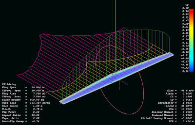
Here is a wing simulation with this airfoil:
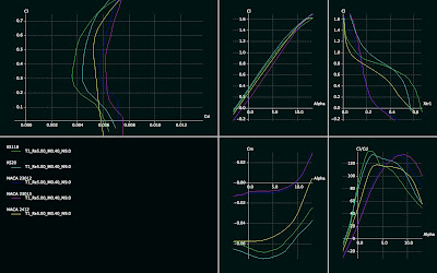
Comparison between NACA and KS118, 2D-simulation
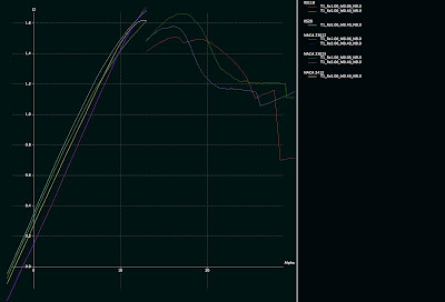
KS118 Cl-alpha polar, including stall region at 1M, comparison with NACA23012 and 23015 included:

KS118.DAT
Here is a wing simulation with this airfoil:

Comparison between NACA and KS118, 2D-simulation

KS118 Cl-alpha polar, including stall region at 1M, comparison with NACA23012 and 23015 included:

Saturday, October 24, 2009
Airfoil investigation database
Pretty neat airfoil database with search and quick illustration capabilities.
http://www.worldofkrauss.com/
http://www.worldofkrauss.com/
Friday, October 23, 2009
How to simulate a wing with QFLR5 -tutorial
1. Batch simulate airfoil for different Reynolds numbers so that the whole range of the wing is covered (speed you want to simulate + chord length on the root and tip). Fast way to calculate Reynolds numbers and mach numbers for your simulation case is to use this web page:
http://aero.stanford.edu/StdAtm.html
Use the metric values.
2. When you know your Mach number and Reynolds number range (ranging from tip to root), simulate the airfoil of your choice on QFLR5 on that range. Using batch analysis feature.
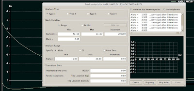
Please note that it can take significant amount of time to batch analysis all the airfoils you want to simulate (e.g. if your wing is going to use more than one airfoil for example, and if you want to compare it to other wings which have different airfoils).
3. Go to Wing and Plane Design. Select from Unit preferences. Replace millimeter units with meter, so you want m/s, m^2, m for length etc.
4. Select Define wing from the menu. A window with a spreadsheet appears.
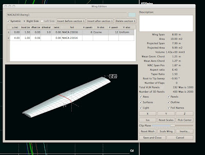
5. Define the wing by entering the y positions (you can define as many as you like). For simple taper it is enough to enter root to y position 0 and then tip to the position where the wing ends. For 12 meters long wing this position is 6 meters (as the plane is quite often symmetric). Select chord length for the root and tip. Select dihedral and twist for the root and tip. Select foil for the root and tip. Select the number of panels you want for the simulation. The more panels, the more accurate. Please note that the dimensions here affect to the Reynolds number, so if your simulation later says it is out of flight envelope, it means that you have not simulated in the Foil direct analysis section the appropriate Reynolds number range, something is missing. Please go back to the web site stated above and check your Reynolds numbers.
6. When you have a wing with desired shape with desired airfoils, click Save and Close from the bottom.
8. Select from Polars menu Define analysis. Select your simulation speed. Please note that this affects your Reynolds number. You need to know at this point your desired speed you want to fly. Select plane weight and moment location on the wing. You can
then select 3D panels. For example I have 150 kt, 800 kg, 0.40 m, 0.00, 0.00.
9. Analysis settings on the right, uncheck sequence if you are interested in one angle of attack only. This most likely is the case if you want to simulate a constant speed (e.g. the 150 kts described above). Then click Analyze and your wing is analyzed for that angle of attack.
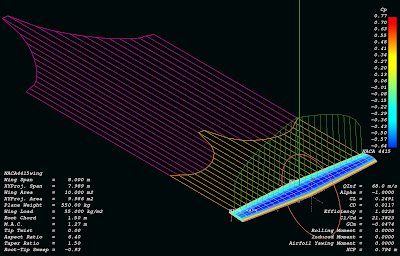
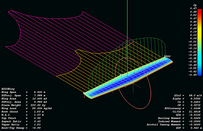
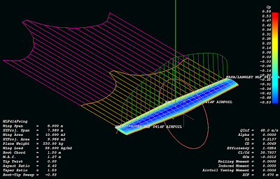
Some examples of analyzed wings:
NACA4415:
KS20 (same wing):
NASA NLF414F (same wing again):
http://aero.stanford.edu/StdAtm.html
Use the metric values.
2. When you know your Mach number and Reynolds number range (ranging from tip to root), simulate the airfoil of your choice on QFLR5 on that range. Using batch analysis feature.

Please note that it can take significant amount of time to batch analysis all the airfoils you want to simulate (e.g. if your wing is going to use more than one airfoil for example, and if you want to compare it to other wings which have different airfoils).
3. Go to Wing and Plane Design. Select from Unit preferences. Replace millimeter units with meter, so you want m/s, m^2, m for length etc.
4. Select Define wing from the menu. A window with a spreadsheet appears.

5. Define the wing by entering the y positions (you can define as many as you like). For simple taper it is enough to enter root to y position 0 and then tip to the position where the wing ends. For 12 meters long wing this position is 6 meters (as the plane is quite often symmetric). Select chord length for the root and tip. Select dihedral and twist for the root and tip. Select foil for the root and tip. Select the number of panels you want for the simulation. The more panels, the more accurate. Please note that the dimensions here affect to the Reynolds number, so if your simulation later says it is out of flight envelope, it means that you have not simulated in the Foil direct analysis section the appropriate Reynolds number range, something is missing. Please go back to the web site stated above and check your Reynolds numbers.
6. When you have a wing with desired shape with desired airfoils, click Save and Close from the bottom.
8. Select from Polars menu Define analysis. Select your simulation speed. Please note that this affects your Reynolds number. You need to know at this point your desired speed you want to fly. Select plane weight and moment location on the wing. You can
then select 3D panels. For example I have 150 kt, 800 kg, 0.40 m, 0.00, 0.00.
9. Analysis settings on the right, uncheck sequence if you are interested in one angle of attack only. This most likely is the case if you want to simulate a constant speed (e.g. the 150 kts described above). Then click Analyze and your wing is analyzed for that angle of attack.
Some examples of analyzed wings:
NACA4415:

KS20 (same wing):

NASA NLF414F (same wing again):

Monday, October 19, 2009
Monday, October 5, 2009
KSNLF51 airfoil - high L/D, high lift, low to medium Re
I created this airfoil one day. I was looking for getting high L/D at low Re. This is pretty nice. I tried simulations as low as Re 100000-300000 (not included in here, you can try by yourself with QFLR5).
Airfoil KSNLF51:

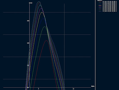
KSNLF51 L/D graph:
Data file: http://www.katix.org/karoliina/airfoils/KSNLF51.DAT
Polars:
Re 1 million, Mach 0.3
http://www.katix.org/karoliina/airfoils/KSNLF51_T1_Re1.00_M0.30_N9.0.txt
Re 3 millions, Mach 0.3
http://www.katix.org/karoliina/airfoils/KSNLF51_T1_Re3.00_M0.30_N9.0.txt
Re 5 millions, Mach 0.3
http://www.katix.org/karoliina/airfoils/KSNLF51_T1_Re5.00_M0.30_N9.0.txt
License: Creative Commons Share-a-like
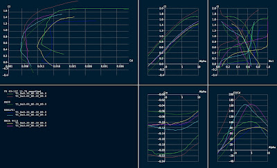
Comparison between some airfoils:
Airfoil KSNLF51:

KSNLF51 L/D graph:

Data file: http://www.katix.org/karoliina/airfoils/KSNLF51.DAT
Polars:
Re 1 million, Mach 0.3
http://www.katix.org/karoliina/airfoils/KSNLF51_T1_Re1.00_M0.30_N9.0.txt
Re 3 millions, Mach 0.3
http://www.katix.org/karoliina/airfoils/KSNLF51_T1_Re3.00_M0.30_N9.0.txt
Re 5 millions, Mach 0.3
http://www.katix.org/karoliina/airfoils/KSNLF51_T1_Re5.00_M0.30_N9.0.txt
License: Creative Commons Share-a-like
Comparison between some airfoils:

Subscribe to:
Comments (Atom)

