http://aero.stanford.edu/StdAtm.html
Use the metric values.
2. When you know your Mach number and Reynolds number range (ranging from tip to root), simulate the airfoil of your choice on QFLR5 on that range. Using batch analysis feature.
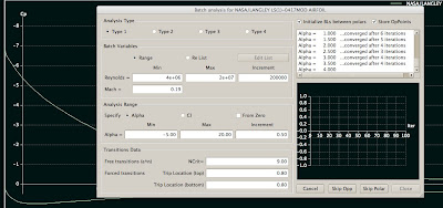
Please note that it can take significant amount of time to batch analysis all the airfoils you want to simulate (e.g. if your wing is going to use more than one airfoil for example, and if you want to compare it to other wings which have different airfoils).
3. Go to Wing and Plane Design. Select from Unit preferences. Replace millimeter units with meter, so you want m/s, m^2, m for length etc.
4. Select Define wing from the menu. A window with a spreadsheet appears.
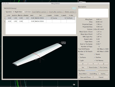
5. Define the wing by entering the y positions (you can define as many as you like). For simple taper it is enough to enter root to y position 0 and then tip to the position where the wing ends. For 12 meters long wing this position is 6 meters (as the plane is quite often symmetric). Select chord length for the root and tip. Select dihedral and twist for the root and tip. Select foil for the root and tip. Select the number of panels you want for the simulation. The more panels, the more accurate. Please note that the dimensions here affect to the Reynolds number, so if your simulation later says it is out of flight envelope, it means that you have not simulated in the Foil direct analysis section the appropriate Reynolds number range, something is missing. Please go back to the web site stated above and check your Reynolds numbers.
6. When you have a wing with desired shape with desired airfoils, click Save and Close from the bottom.
8. Select from Polars menu Define analysis. Select your simulation speed. Please note that this affects your Reynolds number. You need to know at this point your desired speed you want to fly. Select plane weight and moment location on the wing. You can
then select 3D panels. For example I have 150 kt, 800 kg, 0.40 m, 0.00, 0.00.
9. Analysis settings on the right, uncheck sequence if you are interested in one angle of attack only. This most likely is the case if you want to simulate a constant speed (e.g. the 150 kts described above). Then click Analyze and your wing is analyzed for that angle of attack.
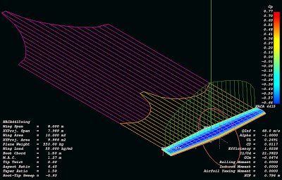
Some examples of analyzed wings:
NACA4415:
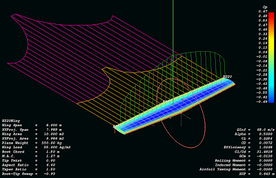
KS20 (same wing):
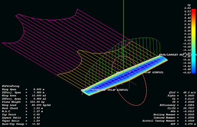
NASA NLF414F (same wing again):
3 comments:
Better to use the Reynolds number list, not the range.
It's roughly logarithmic rather than linear so you don't have to do a thousand polars to get to the high reynolds numbers.
Alternatively, delete all, insert something like 4 million, then just keep inserting before that. The new values are always half the previous. So you get 2 million, 1 million down to 62500...
Also, type 2 polars (fixed weight) rock. Then QFLR varies the angle of attack and flies the plane so fast that it keeps level in the air at that AoA.
I wouldn't analyze just one AoA but a range because of that. You see at what AoA you get the least drag. (or best L/D, remember L=weight in type 2 polars).
Also, the profile polars go MUCH faster if you have less points on the foil. I usually use 60-100 points. Not 265 that results from inverse design. Use global refine in the menu to reduce the number of coordinates.
hi,nice post.Which software is this.
Post a Comment