A funny idea came into my mind. There are couple of Petrel Amphibians in Finland. It looks like a plane of Donald Duck.
Here is one discussion thread in Finnish about it:
Nyt on suomen kolmas akuankkakone valmis
It has staggered wings (two wings, one on top of each other). What if it was completely different. Not exactly completely, but quite completely. Now on this latest Super Petrel, the engine pod is integrated to the upper wing. How if the upper wing was the only wing on the plane, the lower wing would not exist, the upper wing would be twice as long. The tail would not be angled upwards from the bottom of the fuselage, but it would be rather connected with two booms to the wing, in similar manner than it has been done on Adam A500. And finally, but not least, what if the fuselage was not a traditional fuselage, but a pod in the end of a strut, that fits the occupants, and nothing more. It would end before the prop arc. This would allow moving the propeller a bit downwards.
So the result:
- no aerodynamic penalty normally associated with the amphibian planes.
- center of thrust is at the same level as is the lift (high wing)
- because of the boom tail, the tail does not hit the water unless the plane flips.
- because you would not need to fit the tail to the fuselage, the fuselage-pod could be made a better boat shape
I could not resist, but name this idea as Podrel. Actually this is not a new idea entirely, it is partially borrowed from a NASA tech paper, but the application to amphibian use could be new twist for the configuration.
What do you think about this?
Tuesday, September 30, 2008

Dynaero MCR-01
I had a chance to see the Dynaero MCR-01 yesterday at Malmi airport. Here are some interesting pictures about it:
Front:

Dynaero smile:

Back:

Double slotted flaps:

Flap mechanism:

Canopy:

Interesting finding: the upper slot is rigid part of the flap. It does not move by itself, and the mechanism is as simple as on plain flap or the single slotted flap found on Cirrus or Diamond. When the flap is retracted, the slot hides under the wing. Very clever design.
Front:

Dynaero smile:

Back:

Double slotted flaps:

Flap mechanism:

Canopy:

Interesting finding: the upper slot is rigid part of the flap. It does not move by itself, and the mechanism is as simple as on plain flap or the single slotted flap found on Cirrus or Diamond. When the flap is retracted, the slot hides under the wing. Very clever design.
Thursday, September 25, 2008
Good NLF airfoil
The SHM-1 airfoil seems quite interesting. It was designed for Honda Jet. There is a patent about it. I need to investigate that further it seems.
Wednesday, September 24, 2008
Toyota General Aviation aircraft
I found an interesting article about the Toyota general aviation aircraft. It looks like it has been flown again.
Read the arcticle from here:
http://mojaveskies.blogspot.com/2008/07/toyota-in-sky.html
Read the arcticle from here:
http://mojaveskies.blogspot.com/2008/07/toyota-in-sky.html
Wednesday, September 17, 2008
A Lancair builder has collected a list of links to tech papers, e.g. NLF215F
Link:
Interesting technical papers
There is link to the NLF215F airfoil tech paper. It was particularly interesting. Now I understood the philosophy of the profile - I was always wondering, why this profile has the low drag bucket at so high Cl (around 0.5) rather than what is realized in cruise with small aircraft (up to 0.2). But, it seems, that this airfoil is designed to be used with -10 degrees flaps. With those, the low drag bucket gets into the cruise area. Heureka.
Here is a direct link to the paper:
http://www.n91cz.com/Interesting_Technical_Reports/NASA-81-tp1865.pdf
Interesting technical papers
There is link to the NLF215F airfoil tech paper. It was particularly interesting. Now I understood the philosophy of the profile - I was always wondering, why this profile has the low drag bucket at so high Cl (around 0.5) rather than what is realized in cruise with small aircraft (up to 0.2). But, it seems, that this airfoil is designed to be used with -10 degrees flaps. With those, the low drag bucket gets into the cruise area. Heureka.
Here is a direct link to the paper:
http://www.n91cz.com/Interesting_Technical_Reports/NASA-81-tp1865.pdf
Monday, September 15, 2008
X-plane 9 flight simulator available for iPod touch / iPhone
I just downloaded the iPod touch version of the X-plane 9. I am quite impressed about it. It is by far the best mobile game I have ever tried. The controls are done with the accelerometers and throttle and flaps are controlled with two simple finger usable sliders on the screen. The landing gear and brakes have translucent buttons on the bottom of the screen. Everything is fully finger usable as it should.
The aircraft selection consists of Cirrus Vision Jet, Piaggio Avanti, Columbia 400 (that was a positive surprise since it wasn't included with X-plane before), and the C172SP. Needless to say that the Cirrus Jet is the most fun of these to fly.
It is possible to set the weather to IMC, but because the instrument panel does not fit into the tiny screen, it is not included with the sim. Therefore flying IFR approaches with the iPod version is not possible. You can keep the attitude though inside a cloud because of the HUD that includes attitude indicator.
Anyway, this is the best iPod touch app you can find from the App store. It only costs 7.99 eur and is worth every cent. You can find it under games category.
What could be cooler than fly virtual Cirrus Jet in bus when going to work tomorrow?!
The aircraft selection consists of Cirrus Vision Jet, Piaggio Avanti, Columbia 400 (that was a positive surprise since it wasn't included with X-plane before), and the C172SP. Needless to say that the Cirrus Jet is the most fun of these to fly.
It is possible to set the weather to IMC, but because the instrument panel does not fit into the tiny screen, it is not included with the sim. Therefore flying IFR approaches with the iPod version is not possible. You can keep the attitude though inside a cloud because of the HUD that includes attitude indicator.
Anyway, this is the best iPod touch app you can find from the App store. It only costs 7.99 eur and is worth every cent. You can find it under games category.
What could be cooler than fly virtual Cirrus Jet in bus when going to work tomorrow?!
Saturday, September 13, 2008
Twin engine concept, evolved from the single engine concept
Here is what I lofted today in the iRhino:


To make reasonable place for the rear seat/seats, the wing position had to be moved lowish position. The feet of the rear passengers are below the wing spar of the wing.
The rear window is not necessarily in the best place, it might be too much forward. The idea is that the rear seat ends before the prop arc.
The single engine idea in the previous post had apparent CG issues, how to get CG to correct position other than moving the prop completely on top of the fuselage, which moved the engine pod very high. This twin engine version which places the engine pods to the wings, solves this issue obviously.
Here is how it was drawn (in the case someone is interested in learning iRhino):
- The engine pod is NACA 66-025. It is lofted from couple of cross sections which were set along a helper-line which had the airfoil contour.
- The Fuselage is lofted from 5 elliptical cross sections
- The wings are lofted from two airfoil cross sections each
- The tail surfaces are lofted from two airfoil cross sections each
- The canopy and window utilize the Project to Surface -function of the iRhino
- The picture is drawn with correct dimensions. I used measurement -lines to make the parts correct size. The grid was set to 10 cm spacing.
The fuselage height is 86 cm, length is 6.6 meters. I have not yet measured if one can fit inside or not. But basically it resembles a sail plane fuselage. The fuselage may require some scaling up to fit more than two persons inside.


To make reasonable place for the rear seat/seats, the wing position had to be moved lowish position. The feet of the rear passengers are below the wing spar of the wing.
The rear window is not necessarily in the best place, it might be too much forward. The idea is that the rear seat ends before the prop arc.
The single engine idea in the previous post had apparent CG issues, how to get CG to correct position other than moving the prop completely on top of the fuselage, which moved the engine pod very high. This twin engine version which places the engine pods to the wings, solves this issue obviously.
Here is how it was drawn (in the case someone is interested in learning iRhino):
- The engine pod is NACA 66-025. It is lofted from couple of cross sections which were set along a helper-line which had the airfoil contour.
- The Fuselage is lofted from 5 elliptical cross sections
- The wings are lofted from two airfoil cross sections each
- The tail surfaces are lofted from two airfoil cross sections each
- The canopy and window utilize the Project to Surface -function of the iRhino
- The picture is drawn with correct dimensions. I used measurement -lines to make the parts correct size. The grid was set to 10 cm spacing.
The fuselage height is 86 cm, length is 6.6 meters. I have not yet measured if one can fit inside or not. But basically it resembles a sail plane fuselage. The fuselage may require some scaling up to fit more than two persons inside.
Friday, September 12, 2008
Single engine concept
Here is yet another concept illustration. The engine pod would contain HKS700T, Rotax 914 or UlPower 260i with pusher propeller.
The idea of the concept is simplicity, low drag and placing the propeller so that the arc does not get under the plane and thus is not vulnerable to flying dirt etc. like it is usually on pusher designs. The high wing is selected just because that way the center of thrust gets closer to the center of lift and the high thrust line does not cause that high nose down pitching moment. The engine pod fits between the V-tail, which makes the concept similar than the Cirrus Jet.

The major idea in this is that the part count is minimal. There are only two tail surfaces, two wing surfaces, and a single fuselage + pod.
I have done an X-plane model like this. In the model, the control sensitivity is low and the plane maneuvers slowly. It is difficult to make the ailerons and elevators effective enough.
The idea of the concept is simplicity, low drag and placing the propeller so that the arc does not get under the plane and thus is not vulnerable to flying dirt etc. like it is usually on pusher designs. The high wing is selected just because that way the center of thrust gets closer to the center of lift and the high thrust line does not cause that high nose down pitching moment. The engine pod fits between the V-tail, which makes the concept similar than the Cirrus Jet.

The major idea in this is that the part count is minimal. There are only two tail surfaces, two wing surfaces, and a single fuselage + pod.
I have done an X-plane model like this. In the model, the control sensitivity is low and the plane maneuvers slowly. It is difficult to make the ailerons and elevators effective enough.
Thursday, September 11, 2008
Idea: fowler slotted flapelevators, how to improve the efficiency of a tandem wing aircraft
I have been thinking how the efficiency of a tandem wing aircraft could be improved. In tandem wing aircraft the front wing determines pretty much how high total Clmax the aircraft is going to have which translates then to the required wing area. To maximize the efficiency, because flaps can not be used in the rear wing, the Clmax of the front wing is desirable to be as high as possible. Usually on tandem wing and canard aircraft the Clmax of the front wing is around 2.0 and the elevator is a single slotted flap.
It may not be mechanically very practical, but theoretically it could be possible to increase the Clmax of the front wing by adding more high lift devices into it. There could be a fowler flap implemented so that it increases the wing area substantially while the single slotted elevator flap remains working as usual in the trailing edge. The problem is that how you do that when the whole elevator system moves as consequence when the flaps are lowered or raised (the fowler is either inside the wing or protruded out of the trailing edge). But if this was practical with any other means than using servo motors for the elevator too, it could increase the available lift from the front wing somewhat. A challenging thing in this obviously is that the shear web that connects the spar caps goes through the front wing, and the flap system can not break the integrity of the shear web. More limiting factor also is that the chord length of a tandem wing aircraft front wing is low and there is not that much space for the high lift device.
Anyway, it would be interesting to try this out with a radio controlled model.
I hereby license this invention under the terms and conditions of GNU General Public License, version 3, or any later version. (C) 2008 Karoliina Salminen. All rights reserved. By reading this text, you aknowledge this and agree with the terms and conditions of the GPL license.
It may not be mechanically very practical, but theoretically it could be possible to increase the Clmax of the front wing by adding more high lift devices into it. There could be a fowler flap implemented so that it increases the wing area substantially while the single slotted elevator flap remains working as usual in the trailing edge. The problem is that how you do that when the whole elevator system moves as consequence when the flaps are lowered or raised (the fowler is either inside the wing or protruded out of the trailing edge). But if this was practical with any other means than using servo motors for the elevator too, it could increase the available lift from the front wing somewhat. A challenging thing in this obviously is that the shear web that connects the spar caps goes through the front wing, and the flap system can not break the integrity of the shear web. More limiting factor also is that the chord length of a tandem wing aircraft front wing is low and there is not that much space for the high lift device.
Anyway, it would be interesting to try this out with a radio controlled model.
I hereby license this invention under the terms and conditions of GNU General Public License, version 3, or any later version. (C) 2008 Karoliina Salminen. All rights reserved. By reading this text, you aknowledge this and agree with the terms and conditions of the GPL license.
Monday, September 8, 2008
NLF airfoil with low pitching moment
I have been searching the web for such airfoil, and it seems like there is no such thing in the public domain. At least I have not found one.
For a canard/tandem configured aircraft, the main wing should have very low pitching moment, preferably zero if possible. The flying wing airfoils generally don't have very extensive laminar flow and they are not that interesting except for some exceptions (found one Wortmann airfoil which has quite high L/D but does not really compare to the drag coefficient of the NLF414F at high reynolds number).
So what I would be looking for would be:
- a thick (16-20%) low reynolds number natural laminar airfoil which has low or zero pitching moment, has design cruise Cl of 0.1-0.2 and which would have comparable drag charasteristics than the NLF414F or not very much higher drag than the NLF414F and which would have design cruise reynolds number around 5 million (not 10 million like the 414F) and which would achieve unflapped Cl of 1.2...1.3 at reynolds number 0.8 million.
So am I looking for an impossible airfoil? If you know that someone has designed and tested in wind tunnel this kind of airfoil, please let me know!
For a canard/tandem configured aircraft, the main wing should have very low pitching moment, preferably zero if possible. The flying wing airfoils generally don't have very extensive laminar flow and they are not that interesting except for some exceptions (found one Wortmann airfoil which has quite high L/D but does not really compare to the drag coefficient of the NLF414F at high reynolds number).
So what I would be looking for would be:
- a thick (16-20%) low reynolds number natural laminar airfoil which has low or zero pitching moment, has design cruise Cl of 0.1-0.2 and which would have comparable drag charasteristics than the NLF414F or not very much higher drag than the NLF414F and which would have design cruise reynolds number around 5 million (not 10 million like the 414F) and which would achieve unflapped Cl of 1.2...1.3 at reynolds number 0.8 million.
So am I looking for an impossible airfoil? If you know that someone has designed and tested in wind tunnel this kind of airfoil, please let me know!
Friday, September 5, 2008
Dynaero MCR structure description
I have been wondering how the Dynaero wing is constructed specifically. It has aluminum skin and composite structure inside. What kind of structure is pretty nicely described in the following document:
LAA TYPE ACCEPTANCE DATA SHEET TADS 301B, Dynaero MCR01 ULC
LAA TYPE ACCEPTANCE DATA SHEET TADS 301B, Dynaero MCR01 ULC
Friday, August 29, 2008
NACA 66-020, 66-025, 66-030 body drag coefficient
Some numbers from Javafoil using the Drela approximation method (Xfoil after 1991):

NACA 66-020
Parameters: Length 6 meters, diameter from thickest point 1.2 meters:
α Re Cl Cd Cm 0.25 TU TL SU SL L/D A.C.
[°] [-] [-] [-] [-] [-] [-] [-] [-] [-] [-]
0.0 11.60E6 0.000 0.00709 -0.000 0.623 0.623 1.000 1.000 0.000 0.380
So estimated Cd for the fuselage is 0.00709. Doors, antennas, landing gear door, etc. will make it worse.
Bugs and dirt on the fuselage surface and the results becomes:
NACA 66-020
α Re Cl Cd Cm 0.25 TU TL SU SL L/D A.C.
[°] [-] [-] [-] [-] [-] [-] [-] [-] [-] [-]
0.0 11.60E6 0.000 0.01212 -0.000 0.625 0.625 1.000 1.000 0.000 0.380
NACA 66-030 (engine nacelle variant of the laminar body)
m/S = 1
α Re Cl Cd Cm 0.25 TU TL SU SL L/D A.C.
[°] [-] [-] [-] [-] [-] [-] [-] [-] [-] [-]
0.0 11.60E6 0.000 0.00775 -0.000 0.605 0.603 1.000 1.000 0.000 0.456
Cd = 0.00775
With NACA 66-025 the fuselage pod length drops to 4.8 meters.
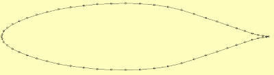
NACA 66-025
m/S = 1
α Re Cl Cd Cm 0.25 TU TL SU SL L/D A.C.
[°] [-] [-] [-] [-] [-] [-] [-] [-] [-] [-]
0.0 9.28E6 0.000 0.00812 -0.000 0.612 0.612 1.000 1.000 0.000 0.417
Cd = 0.00818
Conclusion: All of these pods provide (according to simulation), a low drag coefficient.
Equivalent drag area for NACA 66-025 assuming body diameter of 1.2 meters:
0.00818*(0.6m*0.6m*3.14159) = 0.00925 m^2 (=0.0823 sq ft)
Hmm. did I calculate correctly? Somehow looks quite small.

NACA 66-020
Parameters: Length 6 meters, diameter from thickest point 1.2 meters:
α Re Cl Cd Cm 0.25 TU TL SU SL L/D A.C.
[°] [-] [-] [-] [-] [-] [-] [-] [-] [-] [-]
0.0 11.60E6 0.000 0.00709 -0.000 0.623 0.623 1.000 1.000 0.000 0.380
So estimated Cd for the fuselage is 0.00709. Doors, antennas, landing gear door, etc. will make it worse.
Bugs and dirt on the fuselage surface and the results becomes:
NACA 66-020
α Re Cl Cd Cm 0.25 TU TL SU SL L/D A.C.
[°] [-] [-] [-] [-] [-] [-] [-] [-] [-] [-]
0.0 11.60E6 0.000 0.01212 -0.000 0.625 0.625 1.000 1.000 0.000 0.380
NACA 66-030 (engine nacelle variant of the laminar body)
m/S = 1
α Re Cl Cd Cm 0.25 TU TL SU SL L/D A.C.
[°] [-] [-] [-] [-] [-] [-] [-] [-] [-] [-]
0.0 11.60E6 0.000 0.00775 -0.000 0.605 0.603 1.000 1.000 0.000 0.456
Cd = 0.00775
With NACA 66-025 the fuselage pod length drops to 4.8 meters.

NACA 66-025
m/S = 1
α Re Cl Cd Cm 0.25 TU TL SU SL L/D A.C.
[°] [-] [-] [-] [-] [-] [-] [-] [-] [-] [-]
0.0 9.28E6 0.000 0.00812 -0.000 0.612 0.612 1.000 1.000 0.000 0.417
Cd = 0.00818
Conclusion: All of these pods provide (according to simulation), a low drag coefficient.
Equivalent drag area for NACA 66-025 assuming body diameter of 1.2 meters:
0.00818*(0.6m*0.6m*3.14159) = 0.00925 m^2 (=0.0823 sq ft)
Hmm. did I calculate correctly? Somehow looks quite small.
Evolved aircraft concept requirements
I have a bit evolved set of requirements for an aircraft concept to present. They are now as follows:
- safe
* 2 engines
* 2 fuel systems
* 2 propellers
* non-stallable
* non-spinnable
* double avionics
* two batteries
* two electrical systems
* moderate stall speed (<=55 kts)
* good brakes
* good tires and landing gear that does not break from few bounces
- economical
* very low fuel consumption
* must run on autogas or diesel oil
- at least 2 places with side by side seating, in comfort (enough space in cockpit, a lot more than in a Cessna)
- very long endurance
- capable to high altitude flight
- best glide ratio speed as high as feasible (enabling cruising at L/D max).
- very high best L/D ratio (>=1:25)
- low minimum sink rate
- relatively low power required to keep in level flight
- low drag utilizing extensive laminar flow in the fuselage and wings
- lightning strike protection (copper mesh installed to the whole aircraft)
- utility category (+4.4/-2.2G)
- positively stable in all flight conditions (suitable for IFR flight)
- speed brakes / spoilers
- ballistic recovery chute
- strong roll cage around the cockpit, exceeding the current FAR23 requirement at least with factor of two
- keeping aircraft CG on correct place do not require using ballast (no matter if there are two or one person sitting on front seats)
- aircraft can be parked without anyone sitting on it on its normal upright position
- aircraft shall look stylish and out-of-this-worldish
- surface finish has to be smooth
- large enough control panel for fitting IFR instruments (Large EFIS screen + analog backup instruments)
- good visibility outside
- rudder trim
- aileron trim
- elevator trim
- using aircraft systems has to be simple and all procedures has to be very simple and easy to memorize (aircraft shall not be a checklist-machine)
Summary: Different-looking composite aircraft that incorporates extensive laminar flow, does not stall or spin and that you can fly from Europe to Oskosh and back with ease and with peace of mind. Complies or exceeds with FAR23.
- safe
* 2 engines
* 2 fuel systems
* 2 propellers
* non-stallable
* non-spinnable
* double avionics
* two batteries
* two electrical systems
* moderate stall speed (<=55 kts)
* good brakes
* good tires and landing gear that does not break from few bounces
- economical
* very low fuel consumption
* must run on autogas or diesel oil
- at least 2 places with side by side seating, in comfort (enough space in cockpit, a lot more than in a Cessna)
- very long endurance
- capable to high altitude flight
- best glide ratio speed as high as feasible (enabling cruising at L/D max).
- very high best L/D ratio (>=1:25)
- low minimum sink rate
- relatively low power required to keep in level flight
- low drag utilizing extensive laminar flow in the fuselage and wings
- lightning strike protection (copper mesh installed to the whole aircraft)
- utility category (+4.4/-2.2G)
- positively stable in all flight conditions (suitable for IFR flight)
- speed brakes / spoilers
- ballistic recovery chute
- strong roll cage around the cockpit, exceeding the current FAR23 requirement at least with factor of two
- keeping aircraft CG on correct place do not require using ballast (no matter if there are two or one person sitting on front seats)
- aircraft can be parked without anyone sitting on it on its normal upright position
- aircraft shall look stylish and out-of-this-worldish
- surface finish has to be smooth
- large enough control panel for fitting IFR instruments (Large EFIS screen + analog backup instruments)
- good visibility outside
- rudder trim
- aileron trim
- elevator trim
- using aircraft systems has to be simple and all procedures has to be very simple and easy to memorize (aircraft shall not be a checklist-machine)
Summary: Different-looking composite aircraft that incorporates extensive laminar flow, does not stall or spin and that you can fly from Europe to Oskosh and back with ease and with peace of mind. Complies or exceeds with FAR23.
Wednesday, August 27, 2008
HKS700T info and pictures
Here is the link to information about this very interesting engine:
http://www.apsu-hks.com/HKS_APSU_-_HKS_700T.html
http://www.apsu-hks.com/HKS_APSU_-_HKS_700T.html
Monday, August 25, 2008
Solar plane makes record flight
A solar UAV utilizing Lithium-Sulphur batteries and amorphous silicon solar arrays has made a record flight. Read the BBC NEWS story: BBC: Solar plane makes record flight
Sunday, August 24, 2008
Illustration for the previously mentioned idea
Here is a rough illustration about the configuration layout. This picture is not drawn into any scale dimensions, it is just "artistic" illustration of the idea. I did not draw taper to wings etc. because I wanted to draw it quickly. Here is the picture:

The drawing program is by the way the Rhino3D for MacOSX, a pre-beta -version of it, I am privileged to be a beta-tester.
Basic locations I had in mind:
Seats are in front of the canard wing. The fuel and baggage is stored between the canard and main wing. The engine nacelles are more forward than in the Long-Ez derivatives. They protrude from the main wing forward in a similar manner like they would be additional fuselages in midwing configuration. The engine nacelles are not necessarily fat enough to look realistic, but they hopefully deliver the basic idea, as this is not a final drawing but a computerized sketch of the configuration layout. The two horizontal stabilizers are in the propeller stream because that way they are more effective than winglet mounted rudders would be on a canard aircraft, and instead of becoming effective at relatively high speed, these can be made to be effective from almost zero speed, similarly than conventionally configured aircraft.
The idea is influenced by this:
http://www.scaled.com/projects/proteus_specifications.pdf

The drawing program is by the way the Rhino3D for MacOSX, a pre-beta -version of it, I am privileged to be a beta-tester.
Basic locations I had in mind:
Seats are in front of the canard wing. The fuel and baggage is stored between the canard and main wing. The engine nacelles are more forward than in the Long-Ez derivatives. They protrude from the main wing forward in a similar manner like they would be additional fuselages in midwing configuration. The engine nacelles are not necessarily fat enough to look realistic, but they hopefully deliver the basic idea, as this is not a final drawing but a computerized sketch of the configuration layout. The two horizontal stabilizers are in the propeller stream because that way they are more effective than winglet mounted rudders would be on a canard aircraft, and instead of becoming effective at relatively high speed, these can be made to be effective from almost zero speed, similarly than conventionally configured aircraft.
The idea is influenced by this:
http://www.scaled.com/projects/proteus_specifications.pdf
Saturday, August 23, 2008
A configuration idea for a canard aircraft
Canard configuration is usually quite problematic and it has several compromises which decrease the benefits that could be otherwise obtained from the configuration. However, there is one advantage on canard configuration which is better than traditional configuration: stall and spin resistance. If the major design goal is stall and spin resistance, the penalties from the canard configuration can be assumed acceptable. After all very many aircraft accidents are caused by stall/spin.
So how to do a twin engine propeller canard so that the engine pods can be utilized also to other use?
So the idea goes:
1. take a look at Burt Rutan's Proteus.
2. see the booms for the horizontal stabilizers.
3. Instead of placing jet engines to the fuselage, why not put tractor propellers to the front of the booms.
3. The CG on canard aircraft is between the two wings, the long fuselage solves the problem where to place the fuel in
a canard AC, it can be stored between the wings inside the fuselage.
Any comments/arguments why this would not be a good idea in your opinion?
So how to do a twin engine propeller canard so that the engine pods can be utilized also to other use?
So the idea goes:
1. take a look at Burt Rutan's Proteus.
2. see the booms for the horizontal stabilizers.
3. Instead of placing jet engines to the fuselage, why not put tractor propellers to the front of the booms.
3. The CG on canard aircraft is between the two wings, the long fuselage solves the problem where to place the fuel in
a canard AC, it can be stored between the wings inside the fuselage.
Any comments/arguments why this would not be a good idea in your opinion?
Wednesday, August 20, 2008
Eggenfellner's aircraft project
Eggenfellner seems to be building a new aircraft type:
http://www.eggenfellneraircraft.com/E2B.htm
Interesting design choice - flying wing, no tail. Sounds like no flaps on this machine for increasing Clmax.
http://www.eggenfellneraircraft.com/E2B.htm
Interesting design choice - flying wing, no tail. Sounds like no flaps on this machine for increasing Clmax.
Tuesday, August 19, 2008
Drag coefficient for everyone
It seems that Wikipedia explains drag coefficient quite well. Here are two articles:
http://en.wikipedia.org/wiki/Drag_coefficient
http://en.wikipedia.org/wiki/Drag_equation
Here are NASA's study materials about drag:
http://www.grc.nasa.gov/WWW/K-12/airplane/drageq.html
http://en.wikipedia.org/wiki/Drag_coefficient
http://en.wikipedia.org/wiki/Drag_equation
Here are NASA's study materials about drag:
http://www.grc.nasa.gov/WWW/K-12/airplane/drageq.html
Monday, August 18, 2008
NASA NLF-115-20%
I was changing the parameters in the DesignFoil demo. And got interesting positive change for the NLF-115 airfoil: increasing the thickness to 20%, it does not effect the laminar bucket low Cl area, but it increases the laminar bucket towards higher Cl area. On other airfoils, this change usually moves the low drag bucket upwards to higher Cl, but on this airfoil, the low drag bucket seems to rather extend than move. I was trying it out with Reynolds numbers 2000000, 3000000 and 5000000.
The higher thickness (if the simulation is at all correct) would be favorable for structural reasons. The Burt Rutan's canards also use thick airfoils in the canard wing, the thickness of the original GU25 is 20%. I don't know the exact thickness of Roncz R1145MS and haven't measured (I have the Cozy MKIV plans which have the Roncz airfoil included, so I could measure it if I had time to look at it).
The larger thickness contributes to the strength achieved (only those little glass fiber spar caps are needed instead of very heavy big wing spar or alternatively a wing spar made of carbon fiber).
The higher thickness (if the simulation is at all correct) would be favorable for structural reasons. The Burt Rutan's canards also use thick airfoils in the canard wing, the thickness of the original GU25 is 20%. I don't know the exact thickness of Roncz R1145MS and haven't measured (I have the Cozy MKIV plans which have the Roncz airfoil included, so I could measure it if I had time to look at it).
The larger thickness contributes to the strength achieved (only those little glass fiber spar caps are needed instead of very heavy big wing spar or alternatively a wing spar made of carbon fiber).
Thursday, August 14, 2008
Wednesday, August 13, 2008
Finally found a good airfoil program
I have been trying out about all demo versions available of airfoil programs. Best of them so far has been Xfoil and the Javafoil. However, neither seems to accurately simulate the laminar bucket.
I was surprised to try the Designfoil from Dreesecode: it simulates the laminar bucket, and the demo version also run on Ubuntu Hardy Linux with wine. Excellent, the first windows aircraft software that actually runs on Linux so far.
I was surprised to try the Designfoil from Dreesecode: it simulates the laminar bucket, and the demo version also run on Ubuntu Hardy Linux with wine. Excellent, the first windows aircraft software that actually runs on Linux so far.
Monday, August 11, 2008


Friday, August 8, 2008
Some calculations for plane which would utilize two HKS 700 turbos
I was flying today (as a passanger) to Brussels and I wasn't doing nothing, I had paper, pen and the HP calculator with me. And of course J.D. Anderson's Aircraft performance & design as a reference.
So I ended up with some numbers, but I know already that they are a bit off - since I calculated AR the other way around and got with the K and e I used AR = 10 even if I had chosen that the AR = 14. Therefore the climb performance may be even quite pessimistic. Besides of that I was reading yet another aerodynamics book which stated that e is as high as 0.9 for clean airplane.
However, numbers are: Trimaran configuration, 2 x HKS 700 turbo, 2 places, fuel 200 liters, S = 99 ft^2, MTOW 1980 lbs (maybe 900 kg would still be within limits, haven't checked), AR = 14. Slotted flaps and flapped ailerons. Taper 0.5. Low drag laminar airfoil and 60% laminar fuselage shape and the plane will be quite fast. RG is assumed, gear stored in the pusher prop engine pods.
So I ended up with some numbers, but I know already that they are a bit off - since I calculated AR the other way around and got with the K and e I used AR = 10 even if I had chosen that the AR = 14. Therefore the climb performance may be even quite pessimistic. Besides of that I was reading yet another aerodynamics book which stated that e is as high as 0.9 for clean airplane.
However, numbers are: Trimaran configuration, 2 x HKS 700 turbo, 2 places, fuel 200 liters, S = 99 ft^2, MTOW 1980 lbs (maybe 900 kg would still be within limits, haven't checked), AR = 14. Slotted flaps and flapped ailerons. Taper 0.5. Low drag laminar airfoil and 60% laminar fuselage shape and the plane will be quite fast. RG is assumed, gear stored in the pusher prop engine pods.
Wednesday, August 6, 2008
Another engine, HKS700 turbo - 80 hp turbocharged
Some information about the new 80 hp turbocharged fuel injected HKS 700 can be found from here:
Ilmailu.org forum HKS700 80 hp turbo thread (in Finnish)
Ilmailu.org forum HKS700 80 hp turbo thread (in Finnish)
Monday, August 4, 2008
Interesting diesel engine
Tecnam is considering this engine, and it looks very interesting - it is lightweight and runs on diesel. The power output is similar to Rotax 912 and for the turbocharged version (125 hp) even better than any Rotax can do:
http://ppdgemini.com/
http://ppdgemini.com/
The vmax equation
Here is the equation for calculating the estimated maximum speed of the aircraft concept:


The quest for e
Estimating e seems to not be so trivial and causes lots of thinking - it does not seem to be directly applicable by the book:
Daniel Raymer says in his book that e (Oswald's efficiency factor) is normally between 0.7 and 0.85 (the e that is below 1.0 comes from the deviation from the perfect elliptic lift distribution). Jon Anderson Jr. says on his book Aircraft Performance & Design that on general aviation aircraft, the e is normally 0.6. And in one example aircraft design in the book Anderson then goes and uses e that is 0.9. It has quite large impact on the estimation results, so it would be better to estimate it right.
Then there are multiple equations for estimating e, in Raymer's and Anderson's books. All produce different results, and as a result, the K will be different. And the K has effect on L/Dmax. Interesting enough - the L/Dmax, if the e is estimated with any of the equations provided or assumed as 0.6 as Anderson recommends, the Diamond DA42 Twin Star should have L/D ratio around 12 instead of 18 it in reality has. It has been said that these estimation equations apply only to "normal" aspect ratios. It would be interesting to know what is "normal" aspect ratio - DA42 has AR=12 and the LH10 has AR=14. Maybe that is "higher than normal" then and maybe I have had the privilege to fly "not so normal airplane" when flying the Twin Star. Normal or abnormal, it is an excellent aircraft which is very much fun to fly.
So if I am estimating the L/Dmax of aircraft that has AR=14, and has tapered wing, it seems that quite high e value needs to be picked up. The estimation equation is a heavy generalization though, it does not take into account that on which CL the low drag laminar bucked is (it rather seems that the equations assume turbulent flow).
Daniel Raymer says in his book that e (Oswald's efficiency factor) is normally between 0.7 and 0.85 (the e that is below 1.0 comes from the deviation from the perfect elliptic lift distribution). Jon Anderson Jr. says on his book Aircraft Performance & Design that on general aviation aircraft, the e is normally 0.6. And in one example aircraft design in the book Anderson then goes and uses e that is 0.9. It has quite large impact on the estimation results, so it would be better to estimate it right.
Then there are multiple equations for estimating e, in Raymer's and Anderson's books. All produce different results, and as a result, the K will be different. And the K has effect on L/Dmax. Interesting enough - the L/Dmax, if the e is estimated with any of the equations provided or assumed as 0.6 as Anderson recommends, the Diamond DA42 Twin Star should have L/D ratio around 12 instead of 18 it in reality has. It has been said that these estimation equations apply only to "normal" aspect ratios. It would be interesting to know what is "normal" aspect ratio - DA42 has AR=12 and the LH10 has AR=14. Maybe that is "higher than normal" then and maybe I have had the privilege to fly "not so normal airplane" when flying the Twin Star. Normal or abnormal, it is an excellent aircraft which is very much fun to fly.
So if I am estimating the L/Dmax of aircraft that has AR=14, and has tapered wing, it seems that quite high e value needs to be picked up. The estimation equation is a heavy generalization though, it does not take into account that on which CL the low drag laminar bucked is (it rather seems that the equations assume turbulent flow).
Tuesday, July 8, 2008
Rhino3D for Mac
I am on sick leave and typing this from bed, I have two laptops in the bed right now, my work Linux laptop and Kate's Mac.. I have inner ear inflammation which makes me feel really dizzy if I get up from the bed, so I stay down as much as possible...
I was delighted to notice that there is a MacOSX version of Rhino3D coming. My workmate uses Rhino professionally and he told me about that. I of course straight away went ahead and wanted to become a beta tester. And I got approved as beta tester subsequently. Wow.
Rhino is really interesting piece of software. It took about 30 minutes and I had a NACA 66-018 low drag body modeled.
I was delighted to notice that there is a MacOSX version of Rhino3D coming. My workmate uses Rhino professionally and he told me about that. I of course straight away went ahead and wanted to become a beta tester. And I got approved as beta tester subsequently. Wow.
Rhino is really interesting piece of software. It took about 30 minutes and I had a NACA 66-018 low drag body modeled.
Tuesday, June 24, 2008
What is wrong with sailplane airfoils for powered planes
Everything might look very obvious at first, but after digging more and more, it becomes clearer and clearer what kind of compromises all aircraft are made of and why.
A known thing is that the more efficient the airfoil the higher L/D ratio it has and vice versa. So one could go and find that sailplane airfoils produce very high L/D ratios. There is a little but on that though: Sailplane airfoils commonly achieve the best L/D ratio at higher Cl than what is optimal for a powered aircraft with reasonable wing loading where the cruise Cl is between 0.15 and 0.20. E.g. NLF 215F seems to achieve its L/D max at around Cl 0.5 which is unusually low compared to some other airfoils that require Cl being close to 1.0. That is acceptable for a sailplane that is thermalling at close to the stall speed. However, that is not where one wants to cruise with a powered aircraft, there is usually a requirement to get somewhere in a reasonable time, thus speed has some importance.
I have previously mentioned that the wing loading and cruise Cl has direct relation. The higher the wing loading, the higher the cruise Cl vice versa. Then the speed where the best L/D ratio occurs has a relation to the previous and it also tends to have relation to the top speed.
Diamond DA40 uses Wortmann FX 63-137 airfoil. It has best L/D ratio higher than the optimal < 0.2 (for light wing loading). Therefore the best L/D speed is the same as the approach speed on the aircraft. Similarly on Diamond DA42 Twin Star the same airfoil was used but the wing loading is as high as it is on Cirrus SR20. The result is that the best L/D speed is higher than on DA40, the top speed is higher (it is not only because of the two engines, the two engines produce also more drag than one). Because of the substantially heavier wing loading, the DA42 cruises at higher Cl than the DA40 and it gets closer to the airfoil optimum resulting better aerodynamic efficiency.
Cirrus SR20 is very similar to the DA40 but it has a different airfoil and higher wing loading. That results best L/D ratio speed being 96 kts. SR22 has that value even higher, it is over 100 kts, but it can be misleading that the best glide speed mentioned in the operating handbook is lower than on SR20. That is the best glide speed, it is not the best L/D ratio speed of the airfoil, it is a compromise of the airfoil + fuselage + propeller and in the SR22 the propeller is braking a lot more than on SR20, which alone is enough to explain the lower best glide speed - because of the propeller braking, the SR22 sinks faster, but if there was no propeller, SR22 could have higher glide speed than the SR20. But what this has to do with the topic? The interesting thing is that the Cirrus has different airfoil and higher wing loading and the optimum glide speed is higher than on DA40 which results potential to faster cruise speed than DA40 (whereas it is not exactly the airfoil's best L/D speed because of the mentioned reasons). Providing that there is enough power available, the Cirrus airframe is faster although the larger fuselage cross section and wetted area most likely pretty much diminishes the benefit from the wing, that is also partly a reason why the best cruise speed performance of DA40-180/XL and SR20 is not that much different, SR20 is just slightly faster - the Diamond has better fuselage shape and it simply is a lot smaller aircraft than the Cirrus and size does not tend to come without penalty when it comes to aerodynamic drag.
However, it would be beneficial for efficiency to have an airfoil which could achieve higher L/D ratio at the cruise Cl of the DA40 already. It does not come without penalties of course, the airfoils which have high L/D ratio at low Cl don't necessarily always produce optimal Clmax (which then has also relation to the required wing area which gets back to the stall speed and wing loading).
And it is not all in that, Daniel Raymer notes in his book that usually only 90% of the theoretical Clmax of the airfoil gets realized in practice. Therefore it is a interesting compromise between the wing sizing, and the best L/D at cruise Cl. Daniel Raymer notes in high book that the Cl is one of the hardest things to estimate without experimental data from test flights, and often test flights result in the need of modifications (e.g. if the Clmax in practise is not as good as was predicted, a larger wing is required to meet the maximum stall speed criteria, which is for single engine aircraft 61 kts).
It would be really interesting if someone would have a batch processing functionality in a airfoil program that would ingest the UIUC airfoil database data and simulate through all airfoils and put them into a correct order for the given specification (cruise Cl below 0.2), as high L/D at cruise Cl for a low wing loading, and at the same time, as high Clmax as possible, and at the same time, gentle stall charasteristics at low Reynolds number. And of course, the pitching moment also has some importance, high pitching moment tends to cause more trim drag which reduces the achievable Clmax (of the total airframe) considerably - if the wing can achieve e.g. Clmax 2.2, the airframe may be left to below 1.5 in total because of the download in the tail that is negative lift.
A known thing is that the more efficient the airfoil the higher L/D ratio it has and vice versa. So one could go and find that sailplane airfoils produce very high L/D ratios. There is a little but on that though: Sailplane airfoils commonly achieve the best L/D ratio at higher Cl than what is optimal for a powered aircraft with reasonable wing loading where the cruise Cl is between 0.15 and 0.20. E.g. NLF 215F seems to achieve its L/D max at around Cl 0.5 which is unusually low compared to some other airfoils that require Cl being close to 1.0. That is acceptable for a sailplane that is thermalling at close to the stall speed. However, that is not where one wants to cruise with a powered aircraft, there is usually a requirement to get somewhere in a reasonable time, thus speed has some importance.
I have previously mentioned that the wing loading and cruise Cl has direct relation. The higher the wing loading, the higher the cruise Cl vice versa. Then the speed where the best L/D ratio occurs has a relation to the previous and it also tends to have relation to the top speed.
Diamond DA40 uses Wortmann FX 63-137 airfoil. It has best L/D ratio higher than the optimal < 0.2 (for light wing loading). Therefore the best L/D speed is the same as the approach speed on the aircraft. Similarly on Diamond DA42 Twin Star the same airfoil was used but the wing loading is as high as it is on Cirrus SR20. The result is that the best L/D speed is higher than on DA40, the top speed is higher (it is not only because of the two engines, the two engines produce also more drag than one). Because of the substantially heavier wing loading, the DA42 cruises at higher Cl than the DA40 and it gets closer to the airfoil optimum resulting better aerodynamic efficiency.
Cirrus SR20 is very similar to the DA40 but it has a different airfoil and higher wing loading. That results best L/D ratio speed being 96 kts. SR22 has that value even higher, it is over 100 kts, but it can be misleading that the best glide speed mentioned in the operating handbook is lower than on SR20. That is the best glide speed, it is not the best L/D ratio speed of the airfoil, it is a compromise of the airfoil + fuselage + propeller and in the SR22 the propeller is braking a lot more than on SR20, which alone is enough to explain the lower best glide speed - because of the propeller braking, the SR22 sinks faster, but if there was no propeller, SR22 could have higher glide speed than the SR20. But what this has to do with the topic? The interesting thing is that the Cirrus has different airfoil and higher wing loading and the optimum glide speed is higher than on DA40 which results potential to faster cruise speed than DA40 (whereas it is not exactly the airfoil's best L/D speed because of the mentioned reasons). Providing that there is enough power available, the Cirrus airframe is faster although the larger fuselage cross section and wetted area most likely pretty much diminishes the benefit from the wing, that is also partly a reason why the best cruise speed performance of DA40-180/XL and SR20 is not that much different, SR20 is just slightly faster - the Diamond has better fuselage shape and it simply is a lot smaller aircraft than the Cirrus and size does not tend to come without penalty when it comes to aerodynamic drag.
However, it would be beneficial for efficiency to have an airfoil which could achieve higher L/D ratio at the cruise Cl of the DA40 already. It does not come without penalties of course, the airfoils which have high L/D ratio at low Cl don't necessarily always produce optimal Clmax (which then has also relation to the required wing area which gets back to the stall speed and wing loading).
And it is not all in that, Daniel Raymer notes in his book that usually only 90% of the theoretical Clmax of the airfoil gets realized in practice. Therefore it is a interesting compromise between the wing sizing, and the best L/D at cruise Cl. Daniel Raymer notes in high book that the Cl is one of the hardest things to estimate without experimental data from test flights, and often test flights result in the need of modifications (e.g. if the Clmax in practise is not as good as was predicted, a larger wing is required to meet the maximum stall speed criteria, which is for single engine aircraft 61 kts).
It would be really interesting if someone would have a batch processing functionality in a airfoil program that would ingest the UIUC airfoil database data and simulate through all airfoils and put them into a correct order for the given specification (cruise Cl below 0.2), as high L/D at cruise Cl for a low wing loading, and at the same time, as high Clmax as possible, and at the same time, gentle stall charasteristics at low Reynolds number. And of course, the pitching moment also has some importance, high pitching moment tends to cause more trim drag which reduces the achievable Clmax (of the total airframe) considerably - if the wing can achieve e.g. Clmax 2.2, the airframe may be left to below 1.5 in total because of the download in the tail that is negative lift.
Thursday, June 19, 2008
First person view for RC aircraft - FPV links
FPV pilot home page
Hobby wireless - a shop where you can buy FPV stuff
Youtube video about FPV in operation:
Hobby wireless - a shop where you can buy FPV stuff
Youtube video about FPV in operation:
Friday, June 13, 2008
Wing structural considerations
Martin Hollman's book seems to describe structural calculations of wing in a pretty understandable way. Even I can follow how the resulting equation comes from the integration. I may write some software for spar sizing and layup schedule later after I get the aerodynamics part good enough to be useful. Martin Hollman's book includes Basic language programs for spar sizing etc., but they are not that easy to convert into modern programming languages because they are full of gotos and gosubs and global variables used in a crazy manner (the traditional Basic-spaghetti way). So it seems to be easier to understand the equations first and create the calculation algorithm from scratch by myself.
However, it would be interesting to know how much weight penalty comes from high aspect ratio. I am particularly interested in AR higher than 10 where around 14 would be great, because I am interested in high flight efficiency. However, my structural needs would be for a lot higher speeds than used on gliders, so it would be interesting to know how feasible it is to achieve a structure for AR=14 that can have Va >= 200 mph without adverse effects e.g. like aileron reversal and flutter.
However, it would be interesting to know how much weight penalty comes from high aspect ratio. I am particularly interested in AR higher than 10 where around 14 would be great, because I am interested in high flight efficiency. However, my structural needs would be for a lot higher speeds than used on gliders, so it would be interesting to know how feasible it is to achieve a structure for AR=14 that can have Va >= 200 mph without adverse effects e.g. like aileron reversal and flutter.
I wrote a review in Finnish about Diamond DA40D handling qualities
I got type check out for Diamond DA40D yesterday and I wrote an article about it. I was very pleased with the handling qualities of the aircraft, it has the most well defined control feel than any other plane I have ever flown to the date. If you understand Finnish, you can read the full article from here http://lentokone.blogspot.com/2008/06/kokeiltua-diamond-da40d.html.
Thursday, June 12, 2008
What Reynolds number fits into my car
I was thinking which is the highest Reynolds number I can fit into our car for transportation. And it seems like it goes as low as 136000, which makes 40 km/h stall speed (~10 m/s) in wing chord being 0.2 m and length 2 meters where aspect ratio becomes 10. This would already require two separate wings, joint left and right wing are not feasible to transport. So the airfoil selection gets a new twist, I can not reach 500000 in any meaningful way with high aspect ratio wings on a model that fits into a car. Also the achievable Cl is quite limited on the low Reynolds number and Cd is not as nice as could be achieved with higher Reynolds numbers. Even this is quite overkill as 40 km/h is very fast for a small model aircraft.
Wednesday, June 11, 2008
Comparing different configurations and plotting fuselage cross sections
Each configuration is a different compromise. I have been thinking hard which would work out the best. This may need to be proven to do a design for all the different alternatives as follows:
1. Laminar body fuselage with prop in rear. Boom tail. Front free of protruding elements until the laminar-turbulent transition point. Rotax 914 might fit into the rear of a rotated NACA 66-030 with no (or at least not long) extension shaft needed.
2. Laminar body fuselage shape with prop in the front, potential for laminar flow lost because of the prop disturbing air in the front. Like Stemme S6.
3. Laminar body fuselage with prop in the rear of the tail. Requires extension shaft which is structurally challenging.
Each design would need to be identical (fuselage pod length in Reynolds number should be equal) and the objective would be to investigate which one produces best compromise for low drag and is structurally the best solution (without unacceptable risk of in-flight failing parts (extension shaft in any circumstances must not fail)).
Measuring the difference actually is quite difficult because of the difference in the Reynolds number of a model aircraft and a full size aircraft because it affects quite heavily the laminar low drag area and where the transition to turbulent flow occurs. Also airfoil which is proper for full size aircraft would not work on a model. The NLF414F I discovered earlier does not work with low Reynolds number, it has nasty stall characteristics with low Reynolds number.
What interests me most in this is that how much drag the two tail booms would add. Would the penalty be more than the benefit of achieving laminar flow in the forward fuselage? Is the extension shaft the only way to achieve laminar flow without sacrificing the benefit?
I have been thinking possible concept for a model: try out the boom tail configuration as specified above. Fuselage would be rotated NACA 66-030 with propeller in the rear. Wortmann FX38-153 profile might work with the target Reynolds number range (the wing span and fuselage length would be determined by the interior size of our car, must be able to be disassembled to a size that fits inside for transportation, using a trailer for moving a model aircraft would be overkill). Target aspect ratio could be around 12-14 for main wing. I haven't done any calculations yet though.
I want to also create a plotting program for the fuselage. Martin Hollman's book has a Basic language program listing for a such thing. I am not sure if it is useful actually, I have been thinking how to parametrize a fuselage cross section (often it is not circular but rather boxy with rounded corners or it might have entirely different airfoil shape in horizontal and vertical axis), how to modify the shape of the centerline where the fuselage cross sections are referenced to and how to make the cross section follow a airfoil coordinates, possibly using the same data files that work with X-foil. Making circular or elliptical (LH-10 cross section for example seems to be elliptical) cross section plots from nose to tail for a rotated airfoil wouldn't be that impossible task to do and visualization could be even quite reasonable to do with OpenGL. Before doing the visualization, I however, need to determine how to parametrize it, in other words, how to make it easy to produce differently shaped fuselages. Rhino3D does all this, but I don't have Rhino3D, and this task is not that complicated, it should be doable with some little C++ work.
Any advise on the math and how to make the fuselage design easy would be great, feel free to add comments if you invent something or know something already.
1. Laminar body fuselage with prop in rear. Boom tail. Front free of protruding elements until the laminar-turbulent transition point. Rotax 914 might fit into the rear of a rotated NACA 66-030 with no (or at least not long) extension shaft needed.
2. Laminar body fuselage shape with prop in the front, potential for laminar flow lost because of the prop disturbing air in the front. Like Stemme S6.
3. Laminar body fuselage with prop in the rear of the tail. Requires extension shaft which is structurally challenging.
Each design would need to be identical (fuselage pod length in Reynolds number should be equal) and the objective would be to investigate which one produces best compromise for low drag and is structurally the best solution (without unacceptable risk of in-flight failing parts (extension shaft in any circumstances must not fail)).
Measuring the difference actually is quite difficult because of the difference in the Reynolds number of a model aircraft and a full size aircraft because it affects quite heavily the laminar low drag area and where the transition to turbulent flow occurs. Also airfoil which is proper for full size aircraft would not work on a model. The NLF414F I discovered earlier does not work with low Reynolds number, it has nasty stall characteristics with low Reynolds number.
What interests me most in this is that how much drag the two tail booms would add. Would the penalty be more than the benefit of achieving laminar flow in the forward fuselage? Is the extension shaft the only way to achieve laminar flow without sacrificing the benefit?
I have been thinking possible concept for a model: try out the boom tail configuration as specified above. Fuselage would be rotated NACA 66-030 with propeller in the rear. Wortmann FX38-153 profile might work with the target Reynolds number range (the wing span and fuselage length would be determined by the interior size of our car, must be able to be disassembled to a size that fits inside for transportation, using a trailer for moving a model aircraft would be overkill). Target aspect ratio could be around 12-14 for main wing. I haven't done any calculations yet though.
I want to also create a plotting program for the fuselage. Martin Hollman's book has a Basic language program listing for a such thing. I am not sure if it is useful actually, I have been thinking how to parametrize a fuselage cross section (often it is not circular but rather boxy with rounded corners or it might have entirely different airfoil shape in horizontal and vertical axis), how to modify the shape of the centerline where the fuselage cross sections are referenced to and how to make the cross section follow a airfoil coordinates, possibly using the same data files that work with X-foil. Making circular or elliptical (LH-10 cross section for example seems to be elliptical) cross section plots from nose to tail for a rotated airfoil wouldn't be that impossible task to do and visualization could be even quite reasonable to do with OpenGL. Before doing the visualization, I however, need to determine how to parametrize it, in other words, how to make it easy to produce differently shaped fuselages. Rhino3D does all this, but I don't have Rhino3D, and this task is not that complicated, it should be doable with some little C++ work.
Any advise on the math and how to make the fuselage design easy would be great, feel free to add comments if you invent something or know something already.
Wednesday, May 28, 2008
Relation of cruise Cl and wing loading
It is interesting to look the parameters of different airfoils. One notable thing is that the glide ratio of the given airfoil is in relation to the Cl at cruise condition, and the wing loading has a direct effect to the cruise Cl of the airfoil, the higher the wing loading (the smaller the wing area in relation to weight), the higher is the cruise Cl. With some aifoils, this relation is stronger than with others, since the low drag laminar bucket is at some specific Cl, and it is not always in a favorable position for use in a light aircraft, it may be quite often designed for airliners which have very high wing loadings (and very high stall speed as a result as well, unreasonably high for a personal aircraft, which makes surviving a crash unlikely (which would be unacceptable for a personal single engine aircraft)).
I calculated some rounds of weights, wing areas, wing loadings (I have been calculating with wing loadings between 18 lbs/sqft to 25 lbs/sqft (e.g. Lancair Legacy has 23 lbs/sqft)) and subsequently the Cl-cruise and the L/D at the given Cl. Some airfoils are particularly poor at low Cl whereas at least, if Javafoil is at all to be trusted (the methods it uses aren't very accurate), the already mentioned NLF414F is a rare exception. It has excellent lift/drag relation exactly where it should be in a light aircraft with low wing loading. It would be easier to say for sure, if I could see some wind tunnel data for the NLF414F but so far I haven't found enough information. Also it would be interesting to compare to the Wortmann FX63-137. According to Carmichael [1] it does have good L/D charasteristics, but would be great to be able to determine, how good exactly at Cl 0.1, 0.15 and 0.2 (as this is the usual range in light aircraft). The low drag potential is wasted if it can be only utilized at Cl higher than e.g. 0.4, which is not practical or even quite possible in a lightweight personal high performance aircraft and it is also interesting, that many aircraft that are using airfoils which have very low drag potential, may be operating the airfoil outside the best cruise Cl area, and the result is not that good, not that different, or in many cases worse, than if the airfoil was a low drag traditional one, like NACA 66-212. I haven't found so far the wind tunnel data for the Wortmann either, seems like it is not at least available in the Internet, at least not for free.
I calculated some rounds of weights, wing areas, wing loadings (I have been calculating with wing loadings between 18 lbs/sqft to 25 lbs/sqft (e.g. Lancair Legacy has 23 lbs/sqft)) and subsequently the Cl-cruise and the L/D at the given Cl. Some airfoils are particularly poor at low Cl whereas at least, if Javafoil is at all to be trusted (the methods it uses aren't very accurate), the already mentioned NLF414F is a rare exception. It has excellent lift/drag relation exactly where it should be in a light aircraft with low wing loading. It would be easier to say for sure, if I could see some wind tunnel data for the NLF414F but so far I haven't found enough information. Also it would be interesting to compare to the Wortmann FX63-137. According to Carmichael [1] it does have good L/D charasteristics, but would be great to be able to determine, how good exactly at Cl 0.1, 0.15 and 0.2 (as this is the usual range in light aircraft). The low drag potential is wasted if it can be only utilized at Cl higher than e.g. 0.4, which is not practical or even quite possible in a lightweight personal high performance aircraft and it is also interesting, that many aircraft that are using airfoils which have very low drag potential, may be operating the airfoil outside the best cruise Cl area, and the result is not that good, not that different, or in many cases worse, than if the airfoil was a low drag traditional one, like NACA 66-212. I haven't found so far the wind tunnel data for the Wortmann either, seems like it is not at least available in the Internet, at least not for free.
Saturday, May 17, 2008
Found latest LH-10 flight video from Youtube
Here is the latest test flight video of LH-10 prototype (see earlier article where I blogged about the French new plane with low drag body, tandem seating and high aspect ratio wings, LH-10):
http://fr.youtube.com/watch?v=IJjEoPiv66U
http://fr.youtube.com/watch?v=IJjEoPiv66U
Thursday, May 1, 2008
Pilot Performed Preventative Maintenance in FAA system
FAA system allows pilot maintenance more than EASA/JAA-system.
Here is a list the pilot can do a type certificated aircraft:
- Remove, install and repair tires
- Clean, grease or replace wheel bearings
- Replace defective safety wire or cotter pins
- Lubrication not requiring disassembly other than removal of non-structural items such as access covers, cowlings or fairings
- Replenish hydraulic fluid in the hydraulic and brake reservoirs
- Refinish the airplane interior or exterior (excluding balanced control surfaces) with protective coatings
- Repair interior upholstery and furnishing
- Replace side windows
- Replace bulbs, reflectors and lenses of position and landing lights
- Replace cowling not requiring removal of the propeller
- Replace, clean or set spark plug gap clearance
- Replace any hose connection, except hydraulic connections, with replacement hoses
- Clean or replace fuel and oil strainers, as well as replace or clean filter elements
- Replace prefabricated fuel lines
- Replace the battery and check fluid level and specific gravity
After any of the above work is accomplished, appropriate logbook entries must be made.
Means that pretty much 50 hours maintenance can be made by the pilot, using a mechanic is not necessary. Mechanic is needed for annual.
Here is a list the pilot can do a type certificated aircraft:
- Remove, install and repair tires
- Clean, grease or replace wheel bearings
- Replace defective safety wire or cotter pins
- Lubrication not requiring disassembly other than removal of non-structural items such as access covers, cowlings or fairings
- Replenish hydraulic fluid in the hydraulic and brake reservoirs
- Refinish the airplane interior or exterior (excluding balanced control surfaces) with protective coatings
- Repair interior upholstery and furnishing
- Replace side windows
- Replace bulbs, reflectors and lenses of position and landing lights
- Replace cowling not requiring removal of the propeller
- Replace, clean or set spark plug gap clearance
- Replace any hose connection, except hydraulic connections, with replacement hoses
- Clean or replace fuel and oil strainers, as well as replace or clean filter elements
- Replace prefabricated fuel lines
- Replace the battery and check fluid level and specific gravity
After any of the above work is accomplished, appropriate logbook entries must be made.
Means that pretty much 50 hours maintenance can be made by the pilot, using a mechanic is not necessary. Mechanic is needed for annual.
Friday, April 18, 2008
Airfoil documents
There is an interesting document on Selig's page:
http://www.ae.uiuc.edu/m-selig/uiuc_lsat/vol4/NREL-SR-500-34515.pdf.
It covers for example wind tunnel results for Wortmann FX63-137 at low Reynolds numbers.
Links to NASA tech papers about airfoils
Covers NLF 215F
http://www.ae.uiuc.edu/m-selig/uiuc_lsat/vol4/NREL-SR-500-34515.pdf.
It covers for example wind tunnel results for Wortmann FX63-137 at low Reynolds numbers.
Links to NASA tech papers about airfoils
Covers NLF 215F
Aircraft calculator web page
I found this:
http://anton.panchishin.com/docs/aircraftcalc.html
I am not sure how useful it is, but just for fun, enjoy.
http://anton.panchishin.com/docs/aircraftcalc.html
I am not sure how useful it is, but just for fun, enjoy.
Airspeed at sea level
I got interesting airspeed calculator Excel-sheet from Petri Flander. I have been calculating those things with my aircraft design program and by hand before, but it is surprisingly handy to see the effect of various flat plate drag areas and their effect to the airspeed. Great input for my program which I am writing the UI for with Qt right now, I may do also graphical output for these parameters, would be fun to have. This was actually also useful to reverse-engineer the flat plate drag areas of various aircrafts. For example I came up with 4,7 ft2 for Cirrus SR20 where Lancair ES (=same as Columbia 400) is 4,0, so Cirrus is a slightly less efficient than the Columbia (which is evident also from the performance numbers comparing SR22 and Columbia 400). Interesting is that I came up with 9 for C152, which is a terribly bad figure. And Zenair CH701 produced a number around 18 which was reverse-engineered from real performance numbers I have heard from a Zenair pilot. Couldn't get much worse than that. BD-5 has very low figure of 0,9 and Vmax probe is at 0,3 (these were obtained from elsewhere). A composite BD-5 with rear body laminar flow suction (with more laminar body shape as well) and some high tech airfoil like the NLF414F could be super-efficient. However, the issues with low Reynolds number from Vmax probe apply, it will have seriously dangerous stall charasteristics without modifications to the airfoil or wing.
Here is a copy paste from the sheet with flat plate drag areas from 0.3 (Vmax probe) to 4 (Lancair ES):
Here is a copy paste from the sheet with flat plate drag areas from 0.3 (Vmax probe) to 4 (Lancair ES):
        Aircraft speed, km/h                    Prop eff        0,85    Dens.ratio      1,000       $

Drag area
ft2     25      40      60      80      85      90      100    <- Total hp  (Rotax 914)
4       148     173     198     218     223     227     235     127,053 kts
3,00    163     191     218     240     245     250     259     139,840 kts
2,40    176     205     235     259     264     269     279     150,639037908943        kts
2,30    178     208     238     262     268     273     283     152,791314948939        kts
2,20    181     211     242     266     272     277     287     155,07211859505 kts
2,12    183     214     245     270     275     280     290     156,998677308782        kts
2,10    184     215     246     270     276     281     291     157,495511877874        kts
2,00    187     218     250     275     281     286     296     160,077864487362        kts
1,90    190     222     254     280     285     291     301     162,838370152973        kts
1,80    193     226     259     285     291     296     307     165,799714672936        kts
1,70    197     230     264     290     296     302     313     168,988949701208        kts
1,60    201     235     269     296     302     308     319     172,438652178898        kts
1,50    205     240     275     303     309     315     326     176,188487565227        kts
1,40    210     246     281     310     316     322     334     180,28735558483 kts
1,30    215     252     288     317     324     330     342     184,796395706893        kts
1,20    221     259     296     326     333     339     351     189,793294797389        kts
1,10    228     266     305     336     342     349     361     195,378626469698        kts
1,00    235     275     315     346     353     360     373     201,685471089846        kts
0,90    243     285     326     359     366     373     386     208,894550582996        kts
0,88    245     287     328     361     369     376     389     210,46524527855 kts
0,50    296     346     396     436     445     454     470     254,107770484061        kts
0,31    347     406     465     512     522     532     551     298,003054739616        kts
Wednesday, April 16, 2008
Reference library
Here is list of some of the books I have:
Aerodynamics for Engineers
Fundamentals of Aerodynamics, by John Anderson
MODERN AIRCRAFT DESIGN, Volume 1 5th Edition, by Martin Hollmann.
MODERN AIRCRAFT DESIGN, Volume 2 4th Edition, by Martin Hollmann.
COMPOSITE AIRCRAFT DESIGN. REVISED 2003. By Dr. Hal Loken and Martin Hollmann.
MODERN AIRCRAFT DRAFTING by Eric and Martin Hollmann.
ADVANCED AIRCRAFT DESIGN by Martin Hollmann.
BRUCE CARMICHAEL'S PERSONAL AIRCRAFT DRAG REDUCTION
Aerodynamics for Engineers
Fundamentals of Aerodynamics, by John Anderson
MODERN AIRCRAFT DESIGN, Volume 1 5th Edition, by Martin Hollmann.
MODERN AIRCRAFT DESIGN, Volume 2 4th Edition, by Martin Hollmann.
COMPOSITE AIRCRAFT DESIGN. REVISED 2003. By Dr. Hal Loken and Martin Hollmann.
MODERN AIRCRAFT DRAFTING by Eric and Martin Hollmann.
ADVANCED AIRCRAFT DESIGN by Martin Hollmann.
BRUCE CARMICHAEL'S PERSONAL AIRCRAFT DRAG REDUCTION
- Aircraft Design : A Conceptual Approach
- Daniel P. Raymer / Hardcover / 4th Ed. Published 2006
- Theory of Flight
- Richard Von Mises, Richard Von Mises
- Aircraft Performance and Design
- John D. Anderson / Hardcover / Published 1998
- Sportplane Construction Techniques : A Builder's Handbook (Tony Bingelis Ser.))
- Tony Bingelis; Paperback
Tuesday, April 15, 2008
Interesting aircraft design - LH10
This plane has some of the elements I have been thinking of an efficient aircraft to have:
http://www.lhaviation.com/site_frame/bases_marges/index.htm
Specs promise 200 kts with 100 hp. Lets see. The plane has already flown, but not yet tests that determine top speed.
According to my calculations, providing they are right, this is not that much out of place. This plane in fact, is pretty much like a two place Vmax Probe. If the airflow stays laminar in the fuselage and wings, the 200 kts might be doable. The relation of stall speed and top speed of the 3.77 projected for this plane is a reachable value. Very interesting to see how it performs and if it does not go 200 kts, why. According to what I have read and would estimate, the drag coefficient of the LH10 should be very small unless there is something wrong that causes the airflow to separate.
The view from the LH10 seems to be as spectacular than from a glider. Would be excellent aircraft for flying for fun.
The airfoil used on this aircraft is particularly interesting. Reasons:
- E.g. NLF414F produces very low drag and very high glide ratio, but not without restrictions - the area of usable Reynold's number is limited which limits the chord of the wing to a rather long one, and the wings of the LH10 would already be below that limit. They say that it is a wind turbine airfoil. I haven't tried simulating the wind turbine airfoils yet, it has not occurred to me that they could be actually be useful on aircraft. However, this seems to prove that this was wrong assumption, and they are in the UIUC database for a reason. Lots of airfoils to investigate...
http://www.lhaviation.com/site_frame/bases_marges/index.htm
Specs promise 200 kts with 100 hp. Lets see. The plane has already flown, but not yet tests that determine top speed.
According to my calculations, providing they are right, this is not that much out of place. This plane in fact, is pretty much like a two place Vmax Probe. If the airflow stays laminar in the fuselage and wings, the 200 kts might be doable. The relation of stall speed and top speed of the 3.77 projected for this plane is a reachable value. Very interesting to see how it performs and if it does not go 200 kts, why. According to what I have read and would estimate, the drag coefficient of the LH10 should be very small unless there is something wrong that causes the airflow to separate.
The view from the LH10 seems to be as spectacular than from a glider. Would be excellent aircraft for flying for fun.
The airfoil used on this aircraft is particularly interesting. Reasons:
- E.g. NLF414F produces very low drag and very high glide ratio, but not without restrictions - the area of usable Reynold's number is limited which limits the chord of the wing to a rather long one, and the wings of the LH10 would already be below that limit. They say that it is a wind turbine airfoil. I haven't tried simulating the wind turbine airfoils yet, it has not occurred to me that they could be actually be useful on aircraft. However, this seems to prove that this was wrong assumption, and they are in the UIUC database for a reason. Lots of airfoils to investigate...
Sunday, March 30, 2008
Full span flaps effect on NASA LS417-karoliinamod
I changed the LS(1)-417 so that the trailing edge gap is zero (=sharpest achievable) instead of the large gap present in that airfoil (Janne's Mini-Sytky does not have this gap while Panu's Mini-Sytky has). According to simulation with Javafoil, this decreases the drag quite significantly. The airfoil has good Clmax at the same time with the low drag (approaches almost NLF414F).
I calculated that Clmax of 2.88 is possible with this profile with full span flaps with fowler inboard section.
Quick calculation with aerocalc shows that the following might be theoretically achievable:
AR 9
Clmax 2.88
Wing area 4.6 m2
span 6.4 m
Wing loading 144 kg/m2 29 lbs/sqft
L/D max 22
Stall speed 55 kts
Max level speed 260 kts 480 km/h with Rotax 914 (90 hp required out of 115, max continuous 100 hp->ok)
best glide speed 150 kts
empty weight 366 kg
mtow 666 kg
Idea: Full span flaps
Full span flaps with flapped ailerons:
In board wing has 60% span fowler flaps. Outboard wing, the remaining 40% consists plain flap type flaperons with similar mechanism than used in Mini-Sytky.
deltaClmax_fowler = 0.6 * 1.67 + 0.4 * 0.9 = 1.362
For airfoil with Clmax 1.2 the maximum Clmax on landing configuration is thus 1.32 + 1.362 = 2.68
This allows smaller wing area and higher wing loading to be used without sacrificing takeoff and landing performance too much.
Another variation with single slotted flaps:
deltaClmax_singleslotted = 0.6*1.18 + 0.4*0.9 = 1.06
+1.06 in Clmax still is a very good value and better that would be obtained with full span flaperon (+0.9). For airfoil with Clmax of 1.32 this yields Clmax of 2.37.
This idea has not been tested in practice and is not guaranteed to work.
Effects on aircraft:
Aircraft with 60% span plain flap and Wortman FX 38-153 (no full span high lift device):
Clmax = 1.3 + 0.9*0.6
deltaClmax = 0.54
Clmax => 1.84
86 hp required for 200 kts cruise
wing loading: 92 kg / m2
wing area: 7.2 m2
stall speed: 55 kts
design cruise: 200 kts
Cdtot = 0.011 (with boundary layer suction)
Same aircraft with full span flaperon and Wortman FX 38-153:
Clmax = 1.3+0.9 = 2.20
Same aircraft parameters:
76 hp required for 200 kts cruise
wing loading: 110 kg / m2
wing area: 6 m2
Aircraft with full span flaps with slotted inboard section:
Clmax = 1.3 + 1.06 = 2.36
Same aircraft parameters:
74 hp required for 200 kts cruise
wing loading: 118 kg / m2
wing area: 5.6 m2
Aircraft with full span flaps with fowler inboard section:
Clmax = 1.3 + 1.362 = 2.66
70 hp required for 200 kts cruise
wing area: 5 m2
wing loading: 134 kg / m2
For the most extreme case theoretical savings over usual configuration:
Power = 86-70 = 16 hp (18%)
wing loading: 134-92 = 42 kg/m2 (31%)
wing area: 7.2 m2 - 5 m2 = 2.2 m2 (30%)
Wednesday, March 26, 2008
Karoliina model 1 iteration 1
Karoliina model 1 concept iteration 1
200 kts with Rotax 914
Specs:
2 places: side by by side staggered seating (co-pilot a bit behind pilot)
Configuration: Pusher with Y-tail.
Engine: Rotax 914 115 hp (100 hp continuous), Propeller: Woodcomp SR3000
Body: 60% laminar flow body.
Body laminarity target: 100% laminar flow with suction.
Landing gear: Trigear, retractable nosegear, Steve Wright noselift. Main gear connected to wing spars at 90 degrees angle.
Wing configuration: Conventional, midwing position
Wing loading: 82 kg/m^2 (16.8 lbs/sqft)
Airfoil: NASA NLF(1)414F.
Flap config: Single slotted flaps with external hinges
AR = 10
L/Dmax = 19.8 at 115 kts
L (wing chord) = 0.8 m
wing area = 8 m^2
wing span = 8 m
Re min (stall) = 1829224
Re cruise = 4217074
Re max cruise = 5586254
empty weight = 366 kg
gross weight = 666 kg
fuel capacity = 140 liters
max cruise speed = 200 kts 370 km/h at 7000 feet
stall speed = 50 kts 92 km/h
approach speed = ~70 kts 130 km/h
drag coefficient target = < 0.016 (total drag). Lower is better. With 100% laminar flow body, a much lower drag coefficient might be possible, this figure is conservative.
200 kts with Rotax 914
Specs:
2 places: side by by side staggered seating (co-pilot a bit behind pilot)
Configuration: Pusher with Y-tail.
Engine: Rotax 914 115 hp (100 hp continuous), Propeller: Woodcomp SR3000
Body: 60% laminar flow body.
Body laminarity target: 100% laminar flow with suction.
Landing gear: Trigear, retractable nosegear, Steve Wright noselift. Main gear connected to wing spars at 90 degrees angle.
Wing configuration: Conventional, midwing position
Wing loading: 82 kg/m^2 (16.8 lbs/sqft)
Airfoil: NASA NLF(1)414F.
Flap config: Single slotted flaps with external hinges
AR = 10
L/Dmax = 19.8 at 115 kts
L (wing chord) = 0.8 m
wing area = 8 m^2
wing span = 8 m
Re min (stall) = 1829224
Re cruise = 4217074
Re max cruise = 5586254
empty weight = 366 kg
gross weight = 666 kg
fuel capacity = 140 liters
max cruise speed = 200 kts 370 km/h at 7000 feet
stall speed = 50 kts 92 km/h
approach speed = ~70 kts 130 km/h
drag coefficient target = < 0.016 (total drag). Lower is better. With 100% laminar flow body, a much lower drag coefficient might be possible, this figure is conservative.
Monday, December 3, 2007
Hello
Hello, my name is Karoliina Salminen and the intention of this blog is to follow topics related to light aircraft design. I do have a dream and want to share it with you.
Subscribe to:
Posts (Atom)