I have noticed (well, might be that it is a usual way to use it but I just haven't heard of it) that Teknodur polyurethane paint that can be used to paint composite structures like those on experimental aircraft, can be applied with brush and then perfected with sanding like on applying topcoat (/gelcoat) on a sailplane.
This just works for me, please do not follow if you are not willing to take the responsibility of potentially ruining your paint:
0. Do not use base paint or raw epoxy method, you don't need to fill pinholes, just forget about pinholes with this method! In other words, you can directly apply like this on top of smooth sanded dry micro or automotive polyester filler!
1. Apply thick layer of Teknodur 2 component polyurethane paint (e.g. white) on top of the composite structure. Any other similar polyurethane paint works too (I have also tested with Hempel 2-component boat polyurethane paint). Base paint is not necessary, the Teknodur takes on a bare epoxy surface which is sanded to dull (be sure it is sanded to dull, if it is not, then it will not take, but peels off). Do not use solvent to make the paint thinner, the thick property is desirable. The thick paint blocks the pinholes on the surface below.
2. Let it cure and then inspect. Look, 1 layer of paint and no pinholes! There may be runs, but you can get rid of the runs easily!
3. Wet sand the surface smooth. Use quite coarse grit at this point.
4. Add second layer of Teknodur paint. You can use a bit solvent now, and you will get no pinholes. Try to avoid runs more carefully at this time.
5. Wet sand to completely smooth finish.
Use all available wet sand paper grits up to 2000 if you can find 2000 grit. 1200 grit is fine though.
6. Use polishing compounds to finish the surface to high gloss.
7. Add vax and polish.
A little bit tedious with all the wet sanding, but on the other hand: full control over pinholes, no base needed, and most sanding goes to the paint without harming the critical glass/carbon fabric under it.
I am just in middle of painting a little composite part this way and I have noticed that it works. Before you ruin any large parts by using a method where the paint is misused and done differently than all painters will teach you, please try it to some scrap part first. I have finished two scrap parts like this and they have been in the snow and ice the whole winter without any harm done to the paint surface, so I would guess that this sanding method does not ruin the paint.
I am not sure, but it could be that:
- You would be even better off if you first apply a very thin layer of paint that enters the pinholes. Sand dull. Then don't care about the pinholes, just add the thick layer of paint on top of the thin layer.
On the base and on the first layer, the sanding result does not need to be smoother than 240 grit. Anything more than that is waste of time because the thick paint rounds the minor irregularities.
Pros:
- Polyurethane paint is easy to sand, very very very very easy compared to sanding epoxy
- Runs on polyurethane paint is no big deal, just sand them off in a minute and you are done!
- Quick to finish
- The thick paint is very weather resistant and is as smooth as you sand it
Cons:
- The layer of paint becomes pretty thick and it is heavy, and in some cases might be undesirable.
Monday, April 5, 2010

Thursday, April 1, 2010
Idea: Series hybrid in airplane using auto engine and avoiding the pitfalls of auto conversions
I have been thinking this back and forth now quite some time. This idea is quite simple, the purpose is to fix the most critical problem with auto conversions, achieve better aerodynamics, propeller placement and mass and inertia distribution.
Auto conversions most often fail, no surprise, because of the reduction gear or belt. The core engine is not the root cause in the problems and many problems with the reduction belt or gear system can not be seen beforehand because the dynamics of the vibrations of the engine, propeller and their inertia forces affecting each other is a bit more complicated than one could think at first - it is not that simple to make these parts to last for hundreds or thousands of hours.
So we came up (with Kate, we usually talk with Kate about these things and we kind of invent these things together, I usually happen to be the one who writes them down - and it is usually so that Kate is the opponent into which I test my idea's feasibility before I write it here) with the idea of having a auto engine, possibly a diesel engine, running at constant power, most likely exactly at the optimum point of the engine, always. Then all the power variation would come from the electric motors which would drive the propellers. The idea is that the diesel engine only runs a generator.
The downside of this idea is the additional weight from the generator, batteries, motor controllers, electric motors and the props (depending how many electric motors are used, it is also possible to use just one if that is preferred). However, there are two several things possibly good about this:
- First the diesel engine burns less fuel, resulting smaller fuel tanks.
- Secondly the gearbox system is saved. The gearbox system can be very heavy duty in a high power aircraft engine and they still have tendency to fail. Possibly something like 40-50 kg is saved straight away.
- Thirdly the aerodynamic advantage - optimal aerodynamic shape without using long extension shafts and couplings to deal with the dynamics of the rotating shaft connected to a non-optimally rotating propeller and the power pulses of the diesel engine. Now there is the chance to put the engine anywhere in the airframe where it best fits and propeller drive don't need to be considered at all.
Then there is the redundancy thing. Brushless DC electric motors usually never fail, but the prop can still fail in bad circumstances. Therefore having two independent props for the one diesel engine could be advantageous. Same thing with the batteries - if the diesel engine fails, the batteries could be sized such that the aircraft can fly without the diesel engine for example for 30 minutes in level flight. That might be enough in most cases to get safely on the ground, except on middle of an ocean. The most likely place for the engine to fail is the takeoff. This takeoff stress would never happen with this engine configuration - the engine would be run always at optimum and safe power, never on takeoff power. The extra power for the takeoff can be easily taken from the batteries if they have proper capacity and the electric motors are powerful enough. On takeoff the batteries at full power are not discharging that quickly, because the diesel engine is recharging the batteries at the same time. The takeoff power can be rarely used for longer than 5 minutes on an aircraft equipped with Lycoming engine either, so having a limited period of time for the full power is not that big problem.
Generator and electric motor can have very high efficiency, and the gap to a efficiency of a reduction belt system is not that great. Best electric motors (though heavy ones) are around 98% efficient.
On descent the diesel engine could be shut down providing there was enough battery capacity. The motors could actually regenerate also batteries when the pilot wants to decelerate the plane.
Maintenance cost would be like a single engine aircraft, but the reliability geared towards a twin. Of course there is the one little fine print: the battery pack is expensive and it has an expiration time and date, unfortunately. But nothing is perfect and without compromises.
Any comments about this idea? This surely would not be a racer as the power to weight ratio would be rather poor, but anyhow I am thinking, providing it would be efficient enough to climb adequately, this would be a quite economical thing to fly and also easy conversion-wise, almost stock auto engine would be okay, no reduction gear and prop installation and an assembly that takes the push or pulling loads, would be needed. Also waiting on the airport would not waste any energy, since props can be completely stopped when the plane does not need to move. For example Lycoming IO-360 consumes about the same amount of gasoline per hour when waiting on IFR clearance on the ground than our Toyota Prius car on highway. Consuming zero amount of fuel when still on the ground, but still being ready, would save some liters.
And answer to the question, why diesel and not gasoline when gasoline engines can be run very lean and quite great specific fuel consumption values can be achieved in optimal conditions - it is quite simple: availability of the 100LL/Avgas seems to be becoming poor. There has been three 100LL operators in Finland, but two of them decided to discontinue this year. There is only one left. When that only one decides that it is not profitable enough, there is no 100LL available for anybody and the whole country's fleet of Lycoming and Continental based planes are grounded. The Jet-A1 is not going anywhere, so engine that can burn the jet fuel would be a safe bet. Jet engine, turboprop, or turbofan are out of the question because those are not available in meaningful sizes and power classes - there is not a small turbofan that would have high pressure ratio and bypass ratio available, nobody manufactures such a thing. And it is unlikely anybody will in the future because this personal flying all is a very niche market unfortunately until it changes for better (if it ever does).
The implementation possibilities have challenges; namely no such electric motor available (would require custom motors possibly), etc. And the weight also causes penalty for the efficiency and speed of the plane. But the power to weight ratio will be with this arrangement a lot better than on a pure electric aircraft. And pure electric aircraft is feasible, why an electric aircraft with a generator and a fueltank added would not be.
And by the way, even if it is first of April at the time of writing this, this blog post is not an April fool.
Auto conversions most often fail, no surprise, because of the reduction gear or belt. The core engine is not the root cause in the problems and many problems with the reduction belt or gear system can not be seen beforehand because the dynamics of the vibrations of the engine, propeller and their inertia forces affecting each other is a bit more complicated than one could think at first - it is not that simple to make these parts to last for hundreds or thousands of hours.
So we came up (with Kate, we usually talk with Kate about these things and we kind of invent these things together, I usually happen to be the one who writes them down - and it is usually so that Kate is the opponent into which I test my idea's feasibility before I write it here) with the idea of having a auto engine, possibly a diesel engine, running at constant power, most likely exactly at the optimum point of the engine, always. Then all the power variation would come from the electric motors which would drive the propellers. The idea is that the diesel engine only runs a generator.
The downside of this idea is the additional weight from the generator, batteries, motor controllers, electric motors and the props (depending how many electric motors are used, it is also possible to use just one if that is preferred). However, there are two several things possibly good about this:
- First the diesel engine burns less fuel, resulting smaller fuel tanks.
- Secondly the gearbox system is saved. The gearbox system can be very heavy duty in a high power aircraft engine and they still have tendency to fail. Possibly something like 40-50 kg is saved straight away.
- Thirdly the aerodynamic advantage - optimal aerodynamic shape without using long extension shafts and couplings to deal with the dynamics of the rotating shaft connected to a non-optimally rotating propeller and the power pulses of the diesel engine. Now there is the chance to put the engine anywhere in the airframe where it best fits and propeller drive don't need to be considered at all.
Then there is the redundancy thing. Brushless DC electric motors usually never fail, but the prop can still fail in bad circumstances. Therefore having two independent props for the one diesel engine could be advantageous. Same thing with the batteries - if the diesel engine fails, the batteries could be sized such that the aircraft can fly without the diesel engine for example for 30 minutes in level flight. That might be enough in most cases to get safely on the ground, except on middle of an ocean. The most likely place for the engine to fail is the takeoff. This takeoff stress would never happen with this engine configuration - the engine would be run always at optimum and safe power, never on takeoff power. The extra power for the takeoff can be easily taken from the batteries if they have proper capacity and the electric motors are powerful enough. On takeoff the batteries at full power are not discharging that quickly, because the diesel engine is recharging the batteries at the same time. The takeoff power can be rarely used for longer than 5 minutes on an aircraft equipped with Lycoming engine either, so having a limited period of time for the full power is not that big problem.
Generator and electric motor can have very high efficiency, and the gap to a efficiency of a reduction belt system is not that great. Best electric motors (though heavy ones) are around 98% efficient.
On descent the diesel engine could be shut down providing there was enough battery capacity. The motors could actually regenerate also batteries when the pilot wants to decelerate the plane.
Maintenance cost would be like a single engine aircraft, but the reliability geared towards a twin. Of course there is the one little fine print: the battery pack is expensive and it has an expiration time and date, unfortunately. But nothing is perfect and without compromises.
Any comments about this idea? This surely would not be a racer as the power to weight ratio would be rather poor, but anyhow I am thinking, providing it would be efficient enough to climb adequately, this would be a quite economical thing to fly and also easy conversion-wise, almost stock auto engine would be okay, no reduction gear and prop installation and an assembly that takes the push or pulling loads, would be needed. Also waiting on the airport would not waste any energy, since props can be completely stopped when the plane does not need to move. For example Lycoming IO-360 consumes about the same amount of gasoline per hour when waiting on IFR clearance on the ground than our Toyota Prius car on highway. Consuming zero amount of fuel when still on the ground, but still being ready, would save some liters.
And answer to the question, why diesel and not gasoline when gasoline engines can be run very lean and quite great specific fuel consumption values can be achieved in optimal conditions - it is quite simple: availability of the 100LL/Avgas seems to be becoming poor. There has been three 100LL operators in Finland, but two of them decided to discontinue this year. There is only one left. When that only one decides that it is not profitable enough, there is no 100LL available for anybody and the whole country's fleet of Lycoming and Continental based planes are grounded. The Jet-A1 is not going anywhere, so engine that can burn the jet fuel would be a safe bet. Jet engine, turboprop, or turbofan are out of the question because those are not available in meaningful sizes and power classes - there is not a small turbofan that would have high pressure ratio and bypass ratio available, nobody manufactures such a thing. And it is unlikely anybody will in the future because this personal flying all is a very niche market unfortunately until it changes for better (if it ever does).
The implementation possibilities have challenges; namely no such electric motor available (would require custom motors possibly), etc. And the weight also causes penalty for the efficiency and speed of the plane. But the power to weight ratio will be with this arrangement a lot better than on a pure electric aircraft. And pure electric aircraft is feasible, why an electric aircraft with a generator and a fueltank added would not be.
And by the way, even if it is first of April at the time of writing this, this blog post is not an April fool.
Monday, March 1, 2010
Rutan Proteus photo collection
NASA has nice photo collection. If you like the looks of the Proteus (in my opinion it is one of the most beautiful aircraft ever done), have a look:
http://www.dfrc.nasa.gov/gallery/photo/Proteus/index.html
http://www.dfrc.nasa.gov/gallery/photo/Proteus/index.html
Sunday, February 28, 2010
Airplane design from structural efficiency point of view combined with aerodynamics point of view - multi-domain optimization
So far I have been looking only the aerodynamics side, but it is quite evident that compromises are needed on the aerodynamics side to achieve the best structural efficiency. I think one good example is Virgin Global Flyer (Scaled Composites model 311). I have not analysed yet the structure, but common sense says that trimaran has weight placed more evenly along the wing span avoiding a very large point load in the middle where the single fuselage would normally exist. The trimaran may have more wetted area than a single fuselage, but on the other hand, weight savings in the very high aspect ratio wing and space gains for the extra fuel are in this concept very important factors.
I find the trimaran configuration quite interesting - several different engine placement configurations for example can be used with this configuration without changing the aerodynamic shape of the concept very much. It is also interesting because it allows placement of the main gear away from the center fuselage and thus provides greater stability on the ground when the aspect ratio is high even if there is fuel placed to the wings very far away from the center of gravity. And as can be seen the same design suits several different missions: Global Flyer is very much like White Knight 2 with SpaceShipTwo under it on the center. Almost the same configuration, adapted to different kind of mission for very different kind of parameters (Global Flyer = long range cruise, White Knight 2 = optimized for climb).
Global flyer drawing Google found from some site
Wikipedia has another great photo, this is from front
The configuration is not really so new and not so unproven either, as people might expect, here is one example where a similar configuration has been used a long time ago:
Northrop Widow
The only difference here is that the Northrop Widow was optimized for different mission than either of the abovementioned and that it had piston engines in front of the outer "fuselages" which were interconnected from the tail section similarly than in Adam A500 whereas the Global Flyer and White Knight Two have two separate tails. It is quite apparent why the tails are separate in these aircraft - because the outer fuselages are placed so widely apart from each other, connecting the tails would have made the tail unnecessarily large which would have caused negative effect for the drag despite it would have had fewer intersections. On the other hand, I have been looking different HALE concepts, and it is quite apparent that the number of intersections is not the major drag source in high altitude aircraft, but the induced drag is, and to minimize induced drag, more intersections can be allowed as the penalty from them is lesser than limiting the aspect ratio would be. This is why there are even some concepts considered at the moment which have wing struts - even if everybody knows that they produce drag, in some concepts, the significance of that drag can be proportionally small whereas the increased aspect ratio has major effect on minimizing the total drag of the aircraft. HALE aircraft have to be quite different than those which are designed to cruise at low altitude, the drag percentages of each contributors are quite different and "one size does not fit all".
It is quite interesting area to explore when the structural efficiency is added to the equation in addition to the aerodynamics and the result is a compromise on both structures and aerodynamics instead of being optimized for either aerodynamics or for structures. The mission parameters tend to heavily affect both and best suited results can be achieved by combining these two and by knowing the intended use exactly, potentially bigger gains can be realized than in a concept that is a general purpose in everything (GA = GENERAL aviation).
I find the trimaran configuration quite interesting - several different engine placement configurations for example can be used with this configuration without changing the aerodynamic shape of the concept very much. It is also interesting because it allows placement of the main gear away from the center fuselage and thus provides greater stability on the ground when the aspect ratio is high even if there is fuel placed to the wings very far away from the center of gravity. And as can be seen the same design suits several different missions: Global Flyer is very much like White Knight 2 with SpaceShipTwo under it on the center. Almost the same configuration, adapted to different kind of mission for very different kind of parameters (Global Flyer = long range cruise, White Knight 2 = optimized for climb).
Global flyer drawing Google found from some site
Wikipedia has another great photo, this is from front
The configuration is not really so new and not so unproven either, as people might expect, here is one example where a similar configuration has been used a long time ago:
Northrop Widow
The only difference here is that the Northrop Widow was optimized for different mission than either of the abovementioned and that it had piston engines in front of the outer "fuselages" which were interconnected from the tail section similarly than in Adam A500 whereas the Global Flyer and White Knight Two have two separate tails. It is quite apparent why the tails are separate in these aircraft - because the outer fuselages are placed so widely apart from each other, connecting the tails would have made the tail unnecessarily large which would have caused negative effect for the drag despite it would have had fewer intersections. On the other hand, I have been looking different HALE concepts, and it is quite apparent that the number of intersections is not the major drag source in high altitude aircraft, but the induced drag is, and to minimize induced drag, more intersections can be allowed as the penalty from them is lesser than limiting the aspect ratio would be. This is why there are even some concepts considered at the moment which have wing struts - even if everybody knows that they produce drag, in some concepts, the significance of that drag can be proportionally small whereas the increased aspect ratio has major effect on minimizing the total drag of the aircraft. HALE aircraft have to be quite different than those which are designed to cruise at low altitude, the drag percentages of each contributors are quite different and "one size does not fit all".
It is quite interesting area to explore when the structural efficiency is added to the equation in addition to the aerodynamics and the result is a compromise on both structures and aerodynamics instead of being optimized for either aerodynamics or for structures. The mission parameters tend to heavily affect both and best suited results can be achieved by combining these two and by knowing the intended use exactly, potentially bigger gains can be realized than in a concept that is a general purpose in everything (GA = GENERAL aviation).
Wednesday, February 24, 2010
Austin's jet design
x-plane.com website had looked a bit boring lately, Austin's long and interesting changelogs are hidden deep under the menu structure, looks like a design of a web designer lately.
But luckily yesterday I realized that Austin had added a link on top of the page. Small link on top of the web designer blob and that goes directly into an interesting page. Now today there are two links (as there is 9.50 beta for X-plane available too), but this one was particularly interesting in the topic of this blog: The Laminar Research X-1 Cavallo is conceived
But luckily yesterday I realized that Austin had added a link on top of the page. Small link on top of the web designer blob and that goes directly into an interesting page. Now today there are two links (as there is 9.50 beta for X-plane available too), but this one was particularly interesting in the topic of this blog: The Laminar Research X-1 Cavallo is conceived
Why Diamond uses Wortmann FX63-137?
I have been thinking over and over again why Diamond has chosen the Wortmann high lift airfoil FX63-137 on its aircraft. However, I am suspecting what might be the reason (not confirmed though since anybody on Diamond booth e.g. in Oshkosh is usually never able to answer to my questions). Here is my theory about it:
- The FX63-137 has high L/D at fairly high alpha and thus Cl (as the airfoil is such that the Cl rises rapidly as a function of alpha). This is maybe not the best configuration for cruise where a low drag bucket at low Cl is desirable. On an airfoil which has best L/D at low Cl, the climb has more D component (because high lift devices cause drag) and while getting more L with high lift devices. It might be close to the optimal climb optimisation on the chosen aspect ratio on those planes and compromise is drawn to cruise and it is not seen as a bad thing because competition is not faster but usually slower, it does not take so much to win e.g. a C172 in efficiency and speed after all. So it might be that with a lower drag cruise airfoil e.g. DA42NG with the very heavy diesel engines might have somewhat poorer climb rate on single engine situation or it might not climb alltogether if the airfoil was not optimised to provide low drag on high Cl.
- Comparison between the DA40 and Cirrus SR20 kind of potentially shows this: the Diamond shows significantly better climb rates with a quite similar AR and quite similar wing loading (SR20 takes some toll on that, but not that much in comparison if a light loaded SR20 and heavy loaded DA40 is compared), despite of the fact that the SR20 has more sophisticated flaps and the SR20 has 20 hp more engine power available.
- This can be also evidenced on best climb rate speed: with similar wing loading, the best climb rate speed is much higher on the SR20 than it is on the DA40, which partly indicates that the sweet point in the L/D occurs at lower alpha on SR20 than on DA40. SR20 also requires quite accurate angle of attack and thus speed to climb optimally whereas the DA40 is not that critical which would also indicate that the low drag bucket of the FX63-137 is broader than on the (according to UIUC data site) Roncz airfoil on the SR20.
So this is just my home-brewn theory style thinking, is based on collected information and my experience with flying the Diamond DA40, DA42 and Cirrus SR20 and SR22. I might be wrong as always, but here is some food of thought if you have been thinking why there is this airfoil with high L/D at high Cl and the airfoil also has fairly high pitching moment which some find undesirable because of for example trim drag.
- The FX63-137 has high L/D at fairly high alpha and thus Cl (as the airfoil is such that the Cl rises rapidly as a function of alpha). This is maybe not the best configuration for cruise where a low drag bucket at low Cl is desirable. On an airfoil which has best L/D at low Cl, the climb has more D component (because high lift devices cause drag) and while getting more L with high lift devices. It might be close to the optimal climb optimisation on the chosen aspect ratio on those planes and compromise is drawn to cruise and it is not seen as a bad thing because competition is not faster but usually slower, it does not take so much to win e.g. a C172 in efficiency and speed after all. So it might be that with a lower drag cruise airfoil e.g. DA42NG with the very heavy diesel engines might have somewhat poorer climb rate on single engine situation or it might not climb alltogether if the airfoil was not optimised to provide low drag on high Cl.
- Comparison between the DA40 and Cirrus SR20 kind of potentially shows this: the Diamond shows significantly better climb rates with a quite similar AR and quite similar wing loading (SR20 takes some toll on that, but not that much in comparison if a light loaded SR20 and heavy loaded DA40 is compared), despite of the fact that the SR20 has more sophisticated flaps and the SR20 has 20 hp more engine power available.
- This can be also evidenced on best climb rate speed: with similar wing loading, the best climb rate speed is much higher on the SR20 than it is on the DA40, which partly indicates that the sweet point in the L/D occurs at lower alpha on SR20 than on DA40. SR20 also requires quite accurate angle of attack and thus speed to climb optimally whereas the DA40 is not that critical which would also indicate that the low drag bucket of the FX63-137 is broader than on the (according to UIUC data site) Roncz airfoil on the SR20.
So this is just my home-brewn theory style thinking, is based on collected information and my experience with flying the Diamond DA40, DA42 and Cirrus SR20 and SR22. I might be wrong as always, but here is some food of thought if you have been thinking why there is this airfoil with high L/D at high Cl and the airfoil also has fairly high pitching moment which some find undesirable because of for example trim drag.
Tuesday, December 29, 2009
Cheap aircraft
I have read this report before, but it still remains quite interesting, it is about the FMX-4 Facetmobile: http://www.wainfan.com/pavreport.pdf
Tuesday, December 8, 2009
SpaceShipTwo unveiled
Here is a great article with pictures and video:
http://news.bbc.co.uk/2/hi/science/nature/8400353.stm
Awesomely pretty machine. I would like to fly that thing (as a pilot rather than passenger).
http://news.bbc.co.uk/2/hi/science/nature/8400353.stm
Awesomely pretty machine. I would like to fly that thing (as a pilot rather than passenger).
Sunday, December 6, 2009
MIT course materials online
I found this site quite interesting:
http://ocw.mit.edu/OcwWeb/web/courses/courses/index.htm#AeronauticsandAstronautics
MIT course lecture material online for everybody for free.
http://ocw.mit.edu/OcwWeb/web/courses/courses/index.htm#AeronauticsandAstronautics
MIT course lecture material online for everybody for free.
Sunday, November 15, 2009
PRELIMINARY AERODYNAMIC DESIGN CONSIDERATIONS FOR ADVANCED LAMINAR FLOW AIRCRAFT CONFIGURATIONS
NASA TP PRELIMINARY AERODYNAMIC DESIGN CONSIDERATIONS FOR ADVANCED LAMINAR FLOW AIRCRAFT CONFIGURATIONS can be found from the following link. I found it quite interesting.
http://ntrs.nasa.gov/archive/nasa/casi.ntrs.nasa.gov/19880014362_1988014362.pdf
http://ntrs.nasa.gov/archive/nasa/casi.ntrs.nasa.gov/19880014362_1988014362.pdf
Monday, October 26, 2009
KS118
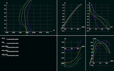
You was able to see the polar of KS118 on the previous blog post. Here is the airfoil in question, it is very similar but slightly different from KS125.

KS118.DAT
Here is a wing simulation with this airfoil:
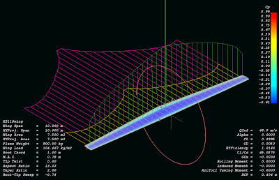
Comparison between NACA and KS118, 2D-simulation
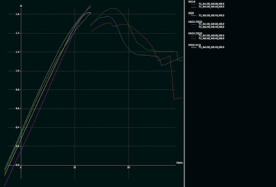
KS118 Cl-alpha polar, including stall region at 1M, comparison with NACA23012 and 23015 included:

KS118.DAT
Here is a wing simulation with this airfoil:

Comparison between NACA and KS118, 2D-simulation

KS118 Cl-alpha polar, including stall region at 1M, comparison with NACA23012 and 23015 included:


Saturday, October 24, 2009
Airfoil investigation database
Pretty neat airfoil database with search and quick illustration capabilities.
http://www.worldofkrauss.com/
http://www.worldofkrauss.com/
Friday, October 23, 2009
How to simulate a wing with QFLR5 -tutorial
1. Batch simulate airfoil for different Reynolds numbers so that the whole range of the wing is covered (speed you want to simulate + chord length on the root and tip). Fast way to calculate Reynolds numbers and mach numbers for your simulation case is to use this web page:
http://aero.stanford.edu/StdAtm.html
Use the metric values.
2. When you know your Mach number and Reynolds number range (ranging from tip to root), simulate the airfoil of your choice on QFLR5 on that range. Using batch analysis feature.
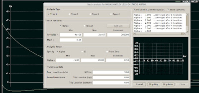
Please note that it can take significant amount of time to batch analysis all the airfoils you want to simulate (e.g. if your wing is going to use more than one airfoil for example, and if you want to compare it to other wings which have different airfoils).
3. Go to Wing and Plane Design. Select from Unit preferences. Replace millimeter units with meter, so you want m/s, m^2, m for length etc.
4. Select Define wing from the menu. A window with a spreadsheet appears.
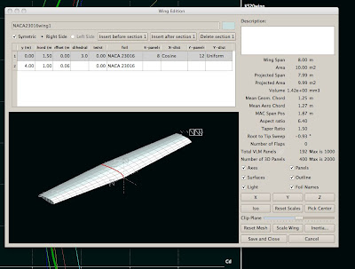
5. Define the wing by entering the y positions (you can define as many as you like). For simple taper it is enough to enter root to y position 0 and then tip to the position where the wing ends. For 12 meters long wing this position is 6 meters (as the plane is quite often symmetric). Select chord length for the root and tip. Select dihedral and twist for the root and tip. Select foil for the root and tip. Select the number of panels you want for the simulation. The more panels, the more accurate. Please note that the dimensions here affect to the Reynolds number, so if your simulation later says it is out of flight envelope, it means that you have not simulated in the Foil direct analysis section the appropriate Reynolds number range, something is missing. Please go back to the web site stated above and check your Reynolds numbers.
6. When you have a wing with desired shape with desired airfoils, click Save and Close from the bottom.
8. Select from Polars menu Define analysis. Select your simulation speed. Please note that this affects your Reynolds number. You need to know at this point your desired speed you want to fly. Select plane weight and moment location on the wing. You can
then select 3D panels. For example I have 150 kt, 800 kg, 0.40 m, 0.00, 0.00.
9. Analysis settings on the right, uncheck sequence if you are interested in one angle of attack only. This most likely is the case if you want to simulate a constant speed (e.g. the 150 kts described above). Then click Analyze and your wing is analyzed for that angle of attack.
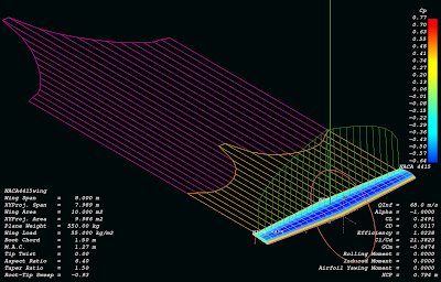
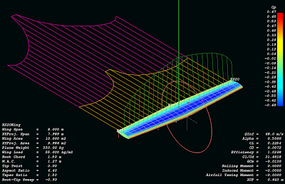
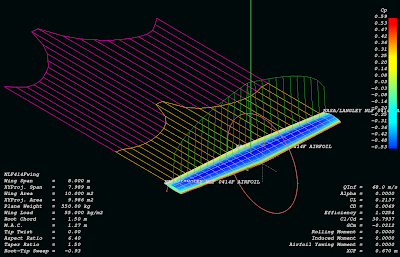
Some examples of analyzed wings:
NACA4415:
KS20 (same wing):
NASA NLF414F (same wing again):
http://aero.stanford.edu/StdAtm.html
Use the metric values.
2. When you know your Mach number and Reynolds number range (ranging from tip to root), simulate the airfoil of your choice on QFLR5 on that range. Using batch analysis feature.

Please note that it can take significant amount of time to batch analysis all the airfoils you want to simulate (e.g. if your wing is going to use more than one airfoil for example, and if you want to compare it to other wings which have different airfoils).
3. Go to Wing and Plane Design. Select from Unit preferences. Replace millimeter units with meter, so you want m/s, m^2, m for length etc.
4. Select Define wing from the menu. A window with a spreadsheet appears.

5. Define the wing by entering the y positions (you can define as many as you like). For simple taper it is enough to enter root to y position 0 and then tip to the position where the wing ends. For 12 meters long wing this position is 6 meters (as the plane is quite often symmetric). Select chord length for the root and tip. Select dihedral and twist for the root and tip. Select foil for the root and tip. Select the number of panels you want for the simulation. The more panels, the more accurate. Please note that the dimensions here affect to the Reynolds number, so if your simulation later says it is out of flight envelope, it means that you have not simulated in the Foil direct analysis section the appropriate Reynolds number range, something is missing. Please go back to the web site stated above and check your Reynolds numbers.
6. When you have a wing with desired shape with desired airfoils, click Save and Close from the bottom.
8. Select from Polars menu Define analysis. Select your simulation speed. Please note that this affects your Reynolds number. You need to know at this point your desired speed you want to fly. Select plane weight and moment location on the wing. You can
then select 3D panels. For example I have 150 kt, 800 kg, 0.40 m, 0.00, 0.00.
9. Analysis settings on the right, uncheck sequence if you are interested in one angle of attack only. This most likely is the case if you want to simulate a constant speed (e.g. the 150 kts described above). Then click Analyze and your wing is analyzed for that angle of attack.
Some examples of analyzed wings:
NACA4415:

KS20 (same wing):

NASA NLF414F (same wing again):

Monday, October 19, 2009
Monday, October 5, 2009
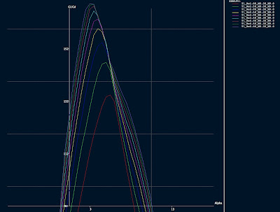
KSNLF51 airfoil - high L/D, high lift, low to medium Re
I created this airfoil one day. I was looking for getting high L/D at low Re. This is pretty nice. I tried simulations as low as Re 100000-300000 (not included in here, you can try by yourself with QFLR5).
Airfoil KSNLF51:

KSNLF51 L/D graph:
Data file: http://www.katix.org/karoliina/airfoils/KSNLF51.DAT
Polars:
Re 1 million, Mach 0.3
http://www.katix.org/karoliina/airfoils/KSNLF51_T1_Re1.00_M0.30_N9.0.txt
Re 3 millions, Mach 0.3
http://www.katix.org/karoliina/airfoils/KSNLF51_T1_Re3.00_M0.30_N9.0.txt
Re 5 millions, Mach 0.3
http://www.katix.org/karoliina/airfoils/KSNLF51_T1_Re5.00_M0.30_N9.0.txt
License: Creative Commons Share-a-like
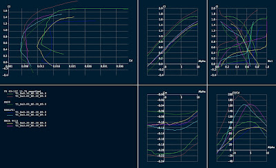
Comparison between some airfoils:
Airfoil KSNLF51:

KSNLF51 L/D graph:

Data file: http://www.katix.org/karoliina/airfoils/KSNLF51.DAT
Polars:
Re 1 million, Mach 0.3
http://www.katix.org/karoliina/airfoils/KSNLF51_T1_Re1.00_M0.30_N9.0.txt
Re 3 millions, Mach 0.3
http://www.katix.org/karoliina/airfoils/KSNLF51_T1_Re3.00_M0.30_N9.0.txt
Re 5 millions, Mach 0.3
http://www.katix.org/karoliina/airfoils/KSNLF51_T1_Re5.00_M0.30_N9.0.txt
License: Creative Commons Share-a-like
Comparison between some airfoils:

Monday, September 21, 2009
Sunday, September 6, 2009
Aerodynamic efficiency index, AEI
I have been trying to come up with my own formula (that differs from the various CAFE formulas to have a weighting that suits me better). I found another interesting comparative formula, the AEI.
AEI = (W0*U0)/hp
where W0 is the gross weight in lbs
where U0 is the free stream velocity in ft/s
where the hp is the horse power required
In other words for Diamond DA40 this is:
W0=1200 kg = 2640 lbs
U0= 214 ft/s (127 kts cruise at 10000 ft)
hp_cruise=90
=>
AEI(Diamond DA40) = (2640*214)/90
AEI(Diamond DA40) = 6277
Unlike the CAFE formula this has no weighting for these parameters.
If I would like to make my formula based on this, I might want to weight the hp a bit more.
That is because the lower the hp figure gets, the better is the fuel economy if everything else remains constant.
Why this index is good? Because it isolates aerodynamics from structural engineering and does not care how much useful load the craft has. It only considers the aerodynamically important point, how much power is required to move the mass forwards and at the same time keep it on air.
AEI = (W0*U0)/hp
where W0 is the gross weight in lbs
where U0 is the free stream velocity in ft/s
where the hp is the horse power required
In other words for Diamond DA40 this is:
W0=1200 kg = 2640 lbs
U0= 214 ft/s (127 kts cruise at 10000 ft)
hp_cruise=90
=>
AEI(Diamond DA40) = (2640*214)/90
AEI(Diamond DA40) = 6277
Unlike the CAFE formula this has no weighting for these parameters.
If I would like to make my formula based on this, I might want to weight the hp a bit more.
That is because the lower the hp figure gets, the better is the fuel economy if everything else remains constant.
Why this index is good? Because it isolates aerodynamics from structural engineering and does not care how much useful load the craft has. It only considers the aerodynamically important point, how much power is required to move the mass forwards and at the same time keep it on air.
Friday, September 4, 2009
AOPA article about Klaus Savier's 100 mpg Vari-Ez
Here is a link to the article by AOPA about Klaus Savier's Vari-Ez.
“For all these guys that think magnetos are so great, I only have one question: Why don’t you put magnetos in your cars?” Read more by clicking the link below:
http://www.aopa.org/aircraft/articles/2008/081230100mpg.html?WT.mc_id=090102epilot&WT.mc_sect=gan
“For all these guys that think magnetos are so great, I only have one question: Why don’t you put magnetos in your cars?” Read more by clicking the link below:
http://www.aopa.org/aircraft/articles/2008/081230100mpg.html?WT.mc_id=090102epilot&WT.mc_sect=gan
Thursday, September 3, 2009
Tuesday, September 1, 2009
TMS turbo installation on Rotax 914
Here is an article about turbo system of the highly modified Rotax:
http://www.designnews.com/article/13660-Turbo_power_reaches_new_heights.php
Interesting web site:
http://www.minijets.org/typo3/index.php
http://www.designnews.com/article/13660-Turbo_power_reaches_new_heights.php
Interesting web site:
http://www.minijets.org/typo3/index.php
Tuesday, August 25, 2009
Tractor vs. pusher
There is lots of strong feelings about tractor vs. pusher propeller configuration but no exact generic answer. Here is one article about the topic. Does not make definitive answer, but gives some background for the topic:
http://www.flyingmag.com/technicalities/1582/pusher-pusher.html
Here is another article:
http://dic.academic.ru/dic.nsf/enwiki/514042
Forum discussion
Another forum discussion
http://www.aiaa.org/content.cfm?pageid=406&gTable=mtgpaper&gID=50663
Tractor (prop forward of laminar flow wing):
http://www.aiaa.org/content.cfm?pageid=406&gTable=Paper&gID=1248
http://www.flyingmag.com/technicalities/1582/pusher-pusher.html
Here is another article:
http://dic.academic.ru/dic.nsf/enwiki/514042
Forum discussion
Another forum discussion
http://www.aiaa.org/content.cfm?pageid=406&gTable=mtgpaper&gID=50663
Tractor (prop forward of laminar flow wing):
http://www.aiaa.org/content.cfm?pageid=406&gTable=Paper&gID=1248
Monday, August 24, 2009
Hypotenuse and catheti and how blending makes wetted area not larger but actually smaller!
Most aircraft have larger than necessary wetted area and not so optimal body shape. One could think without thinking in more detail that wetted area is saved by lofting the plane so that the engine cowling is part of the main fairing and then there is a minimum canopy added on top of that.
However, a little thinking further: which one is the shortest route always, hypotenuse or catheti? Unlike the first thing which comes to mind when looking at planes and saving wetted area, instead of having this complicated shape, actually having more volume and fairing everything in the single form actually produces not only easiest path to the airflow, but also it produces lowest possible wetted area. So making the fuselage larger by removing canopy and putting the cockpit inside the main shape decreases wetted area and drag instead of increasing it. The shallower angle for windows does not decrease the visibility - the visibility can remain still the same. The only problem comes from the optical quality of the windows - as you are looking them from angled direction, you are looking through more plexiglass than you otherwise would and it can degrade the visibility. However - the visibility directly forwards is usually not so good in single engine aircraft which have engine in the front and it is neither better on planes without engine on front since somehow designers seem to not think that people would like to see straight forward very well too. Some twin engine planes have very high panels and poor visibility forwards despite of the fact not having the engine in front would make it possible to make the forward visibility a lot better than that.
So the design on CAD system becomes easy when the shape is not complicated but super simple. And in turn the super simple shape (convex to all directions though, in that sense not so simple, but I mean it is a single loft) has the best drag coefficient and the best wetted area too. At times it feels unbelievable that the solution can be so simple (and I have difficulty to believe it myself when looking e.g. our shared ownership Diamond DA40, it has many shapes, parts and forms), but who says that it has to have so many shapes. Nobody. So it will not have so many different shapes and forms if one shape can do it all. And who says the instrument panel needs to be panel and everything laid out to the panel? Nobody again. A bit more creativity and a lot better forward visibility is achieved despite of not having a bubble canopy and despite of having a pressurized fuselage.
Blending the fuselage to the wings increases frontal area. But who cares about the frontal area. It has very little effect to the drag in airplanes. It is all about wetted area and saving in the wetted area (in addition to maximizing the laminar flow). So blending the wing decreases wetted area - hypotenuse again, it is not a good idea to follow catheti. And the air likes that too - in fuselage wing joint the airflow can not sustain laminar flow. But what if you eliminate the joint and at the same time save in the wetted area. Great stuff.
One could say that it is hard to make a door to a such fuselage. Yes it is hard to make a door. But the solution for the door is to eliminate the door. A hatch that has no hinges and that is larger than the hole is the most light weight door one can imagine. It does not require complicated mechanism to hold it on place and it does not require lots of latches. It holds on place by itself because of the air pressure differential. It can be locked with a lot lesser heavy duty mechanics from inside to the fuselage. And how to ensure the hatch does not ever get out of the hole? That is super easy too: the hole and hatch can be circular and there is no way to put a larger circle out of a smaller circular hole. Not even magicians can do that!
Now then the window problem:
- to glue windows on pressurized fuselage, how to make sure the windows don't rip themselves out - how to glue them on place. Keep it simple and stupid solution: glue them to the inside so that they are larger than the hole in the fuselage. Now what, we have a problem that there is a dent outside of the fuselage on the window area which is really bad for the airflow. No problem again, there can be a simple non-pressurized window that is glued to the outside and faired level with the fuselage around it. It is also a fail-safe: if the windows that are exposed to outside get scratches, no problem, it does not affect the pressurized fuselage - these windows can be replaced fairly easily. And guess what, no bolts are needed, no rivets are needed, very simple.
Then how to get the blended fuselage to work with pressurization. Again super simple: the blend can be fairing on the outside and the pressure vessel can be tubular with completely circular cross section inside.
However, a little thinking further: which one is the shortest route always, hypotenuse or catheti? Unlike the first thing which comes to mind when looking at planes and saving wetted area, instead of having this complicated shape, actually having more volume and fairing everything in the single form actually produces not only easiest path to the airflow, but also it produces lowest possible wetted area. So making the fuselage larger by removing canopy and putting the cockpit inside the main shape decreases wetted area and drag instead of increasing it. The shallower angle for windows does not decrease the visibility - the visibility can remain still the same. The only problem comes from the optical quality of the windows - as you are looking them from angled direction, you are looking through more plexiglass than you otherwise would and it can degrade the visibility. However - the visibility directly forwards is usually not so good in single engine aircraft which have engine in the front and it is neither better on planes without engine on front since somehow designers seem to not think that people would like to see straight forward very well too. Some twin engine planes have very high panels and poor visibility forwards despite of the fact not having the engine in front would make it possible to make the forward visibility a lot better than that.
So the design on CAD system becomes easy when the shape is not complicated but super simple. And in turn the super simple shape (convex to all directions though, in that sense not so simple, but I mean it is a single loft) has the best drag coefficient and the best wetted area too. At times it feels unbelievable that the solution can be so simple (and I have difficulty to believe it myself when looking e.g. our shared ownership Diamond DA40, it has many shapes, parts and forms), but who says that it has to have so many shapes. Nobody. So it will not have so many different shapes and forms if one shape can do it all. And who says the instrument panel needs to be panel and everything laid out to the panel? Nobody again. A bit more creativity and a lot better forward visibility is achieved despite of not having a bubble canopy and despite of having a pressurized fuselage.
Blending the fuselage to the wings increases frontal area. But who cares about the frontal area. It has very little effect to the drag in airplanes. It is all about wetted area and saving in the wetted area (in addition to maximizing the laminar flow). So blending the wing decreases wetted area - hypotenuse again, it is not a good idea to follow catheti. And the air likes that too - in fuselage wing joint the airflow can not sustain laminar flow. But what if you eliminate the joint and at the same time save in the wetted area. Great stuff.
One could say that it is hard to make a door to a such fuselage. Yes it is hard to make a door. But the solution for the door is to eliminate the door. A hatch that has no hinges and that is larger than the hole is the most light weight door one can imagine. It does not require complicated mechanism to hold it on place and it does not require lots of latches. It holds on place by itself because of the air pressure differential. It can be locked with a lot lesser heavy duty mechanics from inside to the fuselage. And how to ensure the hatch does not ever get out of the hole? That is super easy too: the hole and hatch can be circular and there is no way to put a larger circle out of a smaller circular hole. Not even magicians can do that!
Now then the window problem:
- to glue windows on pressurized fuselage, how to make sure the windows don't rip themselves out - how to glue them on place. Keep it simple and stupid solution: glue them to the inside so that they are larger than the hole in the fuselage. Now what, we have a problem that there is a dent outside of the fuselage on the window area which is really bad for the airflow. No problem again, there can be a simple non-pressurized window that is glued to the outside and faired level with the fuselage around it. It is also a fail-safe: if the windows that are exposed to outside get scratches, no problem, it does not affect the pressurized fuselage - these windows can be replaced fairly easily. And guess what, no bolts are needed, no rivets are needed, very simple.
Then how to get the blended fuselage to work with pressurization. Again super simple: the blend can be fairing on the outside and the pressure vessel can be tubular with completely circular cross section inside.
Saturday, August 22, 2009
First atlantic crossing completed
We completed the first atlantic crossing in the N756DS (Diamond DA40) on Wednesday and arrived to Helsinki-Malmi. There will be a presentation about the trip in SIL-luokka Helsinki-Malmi later. I will let you know more about it when I know more details and have prepared the presentation. If you are a reporter in a newspaper or magazine and want to write a story about our not so ordinary adventure, feel free to contact me karoliina dot t dot salminen at gmail dot com.
We received the ferry flight training from Edward Carlson.
We want to do the trip again also, if you are looking for inexpensive ferrying from USA to Finlandm or to any other European country via Denmark/Opmas, I am glad to inform that the Danish VAT will work still to next summer as followings: if you buy aircraft this year before the end of the year and complete all the agreements, according to Opmas, the plane can still benefit from the Danish VAT if it is ferried on the first half of 2010. We would be glad to help for free (no ferry flight fee) at the price of the expenses (gasoline, hotel (we choose cheapest options always), maintenance needed for the plane, airport fees). If you are interested in inexpensive ferry (or should I say delivery) flight, please contact me to the abovementioned address. You can not fly the North Atlantic for first time by yourself, but you need someone that has flown it before to get insurance (which is mandatory for the flight). We have now flown it once and are willing to help people who haven't flown it yet and/or who do not want to fly it by themselves. The summer time is the best time for ferrying an aircraft because of weather. We will spend our summer vacation for flying your plane for free, you can not get better deal from anybody. We agree to fly the following aircraft make and models: Diamond DA40-180/G1000, Diamond DA40XL/G1000, Diamond DA40-CS/G1000, Diamond DA40-180/Avidyne, Cirrus SR20/Avidyne, Cirrus SR22/Avidyne, Cirrus SR22/Garmin Perspective or Diamond or Cirrus with any other comparable glass cockpit avionics - this list is based on our prior flying experience - we have flown Diamonds and Cirruses before. We can consider also other aircraft, but that will rise the expenses a bit since we need to get checked out to these prior flying the trip. I could estimate that most familiar of those would be Columbia 350, Columbia 400, Cessna 350 Corvalis, Cessna 400 Corvalis and these we would be glad to fly providing that we would get proper check-out before starting the trip to feel comfortable enough flying the plane in not so ideal conditions. We may not agree to fly steam-gauge IFR planes and surely will not agree to fly VFR-only equipped planes. Also we will not fly C172, because that is not suitable for the trip. We are not interested in taking unnecessary risks, we want to deliver.
We received the ferry flight training from Edward Carlson.
We want to do the trip again also, if you are looking for inexpensive ferrying from USA to Finlandm or to any other European country via Denmark/Opmas, I am glad to inform that the Danish VAT will work still to next summer as followings: if you buy aircraft this year before the end of the year and complete all the agreements, according to Opmas, the plane can still benefit from the Danish VAT if it is ferried on the first half of 2010. We would be glad to help for free (no ferry flight fee) at the price of the expenses (gasoline, hotel (we choose cheapest options always), maintenance needed for the plane, airport fees). If you are interested in inexpensive ferry (or should I say delivery) flight, please contact me to the abovementioned address. You can not fly the North Atlantic for first time by yourself, but you need someone that has flown it before to get insurance (which is mandatory for the flight). We have now flown it once and are willing to help people who haven't flown it yet and/or who do not want to fly it by themselves. The summer time is the best time for ferrying an aircraft because of weather. We will spend our summer vacation for flying your plane for free, you can not get better deal from anybody. We agree to fly the following aircraft make and models: Diamond DA40-180/G1000, Diamond DA40XL/G1000, Diamond DA40-CS/G1000, Diamond DA40-180/Avidyne, Cirrus SR20/Avidyne, Cirrus SR22/Avidyne, Cirrus SR22/Garmin Perspective or Diamond or Cirrus with any other comparable glass cockpit avionics - this list is based on our prior flying experience - we have flown Diamonds and Cirruses before. We can consider also other aircraft, but that will rise the expenses a bit since we need to get checked out to these prior flying the trip. I could estimate that most familiar of those would be Columbia 350, Columbia 400, Cessna 350 Corvalis, Cessna 400 Corvalis and these we would be glad to fly providing that we would get proper check-out before starting the trip to feel comfortable enough flying the plane in not so ideal conditions. We may not agree to fly steam-gauge IFR planes and surely will not agree to fly VFR-only equipped planes. Also we will not fly C172, because that is not suitable for the trip. We are not interested in taking unnecessary risks, we want to deliver.
Sunday, August 16, 2009
First Northern Atlantic Crossing
I have been recently a bit silent on this blog. The reason have been that I have been too busy and out of Internet most of the time. In other words, I have been flying.
I am typing this from Iceland. Our trip has been so far quite incredible:
1. from Helsinki to Miami with airliner
2. from Miami to Jacksonville with car
3. from Jacksonville to St. Louis with plane, N756DS
4. from St. Louis to Pueblo with N756DS
5. from Pueblo to Palo Alto with N756DS
6. IFR training in San Francisco Bay Area with N756DS
7. from Palo Alto to Sioux Falls with N756DS
8. from Sioux Falls to Oshkosh with N756DS
9. spent couple of days in Oskosh/Airventure 2009. Camp with Cozygirrrls.
10. from Oshkosh to Rhode Island with N756DS
11. from Rhode Island to Wabush (Canada) with N756DS. First Northern Atlantic Crossing in a small airplane was started for us. We are flying with Ed Carlson (he is a ferry flight instructor specialized in Northern Atlantic crossing).
12. from Wabush to Kuujjaq (Canada) with N756DS
13. from Kuujjaq (Canada) to Iqaluit (Canada) with N756DS
14. from Iqaluit (Canada) to Kangerlussuaq (Greenland) with N756DS
15. from Kangerlussuaq (Greenland) to Kulusuk (Greenland) with N756DS
16. from Kulusuk (Greenland) to Reykjavik (Iceland) with N756DS
17. from Reykjavik (Iceland) to EGILSSTADIR with N756DS
We will continue to Faroe Island / Vagar next. After that is either Bergen or Stavanger in Norway.
Kate has been keeping a blog about the adventure here:
http://n756ds.blogspot.com
I am typing this from Iceland. Our trip has been so far quite incredible:
1. from Helsinki to Miami with airliner
2. from Miami to Jacksonville with car
3. from Jacksonville to St. Louis with plane, N756DS
4. from St. Louis to Pueblo with N756DS
5. from Pueblo to Palo Alto with N756DS
6. IFR training in San Francisco Bay Area with N756DS
7. from Palo Alto to Sioux Falls with N756DS
8. from Sioux Falls to Oshkosh with N756DS
9. spent couple of days in Oskosh/Airventure 2009. Camp with Cozygirrrls.
10. from Oshkosh to Rhode Island with N756DS
11. from Rhode Island to Wabush (Canada) with N756DS. First Northern Atlantic Crossing in a small airplane was started for us. We are flying with Ed Carlson (he is a ferry flight instructor specialized in Northern Atlantic crossing).
12. from Wabush to Kuujjaq (Canada) with N756DS
13. from Kuujjaq (Canada) to Iqaluit (Canada) with N756DS
14. from Iqaluit (Canada) to Kangerlussuaq (Greenland) with N756DS
15. from Kangerlussuaq (Greenland) to Kulusuk (Greenland) with N756DS
16. from Kulusuk (Greenland) to Reykjavik (Iceland) with N756DS
17. from Reykjavik (Iceland) to EGILSSTADIR with N756DS
We will continue to Faroe Island / Vagar next. After that is either Bergen or Stavanger in Norway.
Kate has been keeping a blog about the adventure here:
http://n756ds.blogspot.com
Sunday, June 28, 2009
Sunday, June 7, 2009
LINK: How to design blended wing body RC airplane
http://rcairplanedesign.googlepages.com/Design-BWB-Blended-Wing-Body-RCplane.htm
The mentioned AVL can be found from the following address:
http://web.mit.edu/drela/Public/web/avl/
The mentioned AVL can be found from the following address:
http://web.mit.edu/drela/Public/web/avl/
Thursday, June 4, 2009
Sunday, May 31, 2009
Misc tech paper etc. link collection
I created a wiki page to katix gforge for link collection.
I hope you like it. It is not sorted in any sense, but it contains lots of interesting links. A friend of mine has been sending these to me a quite long time and I thought that I could share the collection with you.
http://gforge.katix.org/gf/project/twinzygger/wiki/?pagename=MiscTechPapers
I hope you like it. It is not sorted in any sense, but it contains lots of interesting links. A friend of mine has been sending these to me a quite long time and I thought that I could share the collection with you.
http://gforge.katix.org/gf/project/twinzygger/wiki/?pagename=MiscTechPapers
Wednesday, May 27, 2009
Tailed blended wing body with laminar flow body and Goldschmied suction and pressure thrust
New idea:
- A body that comprises of a laminar body and wing blended together
- There is a V-tail in a blended boom
- Rear of the center section has suction slot on top side
- The boom contains a electric fan that is used for suction and additional thrust
- There are two turbocharged Rotax 912UL engines in the wings which are hidden in blended pods that continue the airfoil shape of the wing without interruption
- Both engines turn additional turbochargers which drive generators which generate electricity for the rear fan of the aircraft
Items that need to be studied:
- does pressure thrust work with this kind of shape, or does it require axisymmetric body?
- compare the drag of minimum axisymmetric body with non-blended wings to a blended wing body which has larger cross sectional area, but potentially lower wetted area.
- wing incidence relative to the center section - center section has a lower aspect ratio than the wings and what it requires to achieve optimal lift distribution in this combined case
- the achievable gain from the lack of interference drag or very small interference drag
- optimal wing loading for a combined blended wing body compared to a pod+boom+wings solution
- shark fin shape on the outer wing sections, the gain and the issues
- A body that comprises of a laminar body and wing blended together
- There is a V-tail in a blended boom
- Rear of the center section has suction slot on top side
- The boom contains a electric fan that is used for suction and additional thrust
- There are two turbocharged Rotax 912UL engines in the wings which are hidden in blended pods that continue the airfoil shape of the wing without interruption
- Both engines turn additional turbochargers which drive generators which generate electricity for the rear fan of the aircraft
Items that need to be studied:
- does pressure thrust work with this kind of shape, or does it require axisymmetric body?
- compare the drag of minimum axisymmetric body with non-blended wings to a blended wing body which has larger cross sectional area, but potentially lower wetted area.
- wing incidence relative to the center section - center section has a lower aspect ratio than the wings and what it requires to achieve optimal lift distribution in this combined case
- the achievable gain from the lack of interference drag or very small interference drag
- optimal wing loading for a combined blended wing body compared to a pod+boom+wings solution
- shark fin shape on the outer wing sections, the gain and the issues
Saturday, May 23, 2009
Thursday, May 21, 2009
High transition length NLF body
I was looking Parson's high transition length body in a book and thought that maybe if I modify my body shape also so that the nose becomes sharper. By sacrificing some interior space, the flow acceleration can be kept for high transition length according the book I was reading this. My modified body looks like this.

Despite the QFLR5 algorithm is not maybe designed for simulating NLF bodies (it is designed for simulating wings), the pressure distribution looks like the same as the wind tunnel data for the Parson's body which makes me think that it might not be that much wrong.

Despite the QFLR5 algorithm is not maybe designed for simulating NLF bodies (it is designed for simulating wings), the pressure distribution looks like the same as the wind tunnel data for the Parson's body which makes me think that it might not be that much wrong.
Wednesday, May 20, 2009
Wolfram
Ever wanted a Star Trek's computer? It is here today:
http://www.wolframalpha.com/
For starters, try out for example: integrate x+y^2
This service is superb.
http://www.wolframalpha.com/
For starters, try out for example: integrate x+y^2
This service is superb.
Thursday, May 14, 2009
Random thinking about the feasibility of fabrication of a partial pressure suit
I have been thinking this topic for quite a long time and my old conclusion was that it is not feasible. However, there is very little information about pressure suits out there, but looking at the very little there is about the old Mercury suits etc., I have got indications that actually fabrication of a partial pressure suit might be feasible. Buying one might not be feasible because of lack of availability and insane pricing.
I would like to learn more about the topic, but in the Internet at least, there is very little or nothing. If someone has some insight, please leave some comments.
I would like to learn more about the topic, but in the Internet at least, there is very little or nothing. If someone has some insight, please leave some comments.
Wednesday, May 13, 2009
Fuselage drag reduction principle

A major portion of aircraft drag (in addition to the wing) is generated by the fuselage. The poor aircraft has to drag the draggy fuselage forwards. It is justified to target for reducing the fuselage drag in addition to the drag of the wings to achieve high L/D ratio and thus high efficiency and exceptional miles per gallon figure.
The idea comprises of the following claims:
- a laminar body with optimal fineness ratio for minimum drag
- a tail boom behind the optimal fineness ratio laminar pod
- electric motor (or couple of electric motors in cascade) turn
one or many ducted fans that are in cascade inside the rear of the fuselage.
The fan(s) take their air intake from the boundary layer of the fuselage.
- the fans are driven with batteries on takeoff.
- the fans are driven in cruise with electricity generated from the exhaust gas of the two gasoline engines which are mounted in wings.
- there is an additional turbine mounted in the exhaust that turns a generator rather than compressing air for the gasoline engine.
- the exhaust for the air is either in the tail boom prior to the tail or after the tail, whichever is found to provide best results.
- the fans provide suction for the fuselage boundary layer and also additional thrust for the aircraft. This configuration however, does not cause additional drag for the aircraft but reduces it.
- additional generators can be mounted to wing tip vortices so that the wing tip vortex turns the turbine blades and thus generates electricity for the fans located in the rear of the fuselage.
- the generators, battery charging and fans are computer controlled.
- the fans utilize all power that can be drawn from the exhaust gas and the wing tip turbines and thus runs at full power available to it continuously. On takeoff batteries are used to ensure high centerline thrust for the hypothetical situation where one of the gasoline engines would fail.
Goldschmied papers online
I found these some time ago, but now got reminded about it also on one comment to a previous post. Therefore I decided to open a new topic for it:
Goldschmied drag reduction tech papers:
http://cafefoundation.org/v2/pav_enablingtech_dragreduction.php
Interesting reading for anyone interested in achieving major breakthroughs in the fuselage drag.
Goldschmied drag reduction tech papers:
http://cafefoundation.org/v2/pav_enablingtech_dragreduction.php
Interesting reading for anyone interested in achieving major breakthroughs in the fuselage drag.
Thursday, May 7, 2009

Looking at historical data
One interesting aircraft in the historical data:
Lancair Evolution
P/W Power to weight ratio 7.54 kg/kW, 12.28 lbs/hp.
W/S Wing loading 142 kg/m^2, 29.05 lbs/sqft
Stall speed 61 kts
Empty weight to gross weight ratio: 0.55
Fuel to gross weight ratio: 0.2
Aspect ratio: 10.3
Aircraft with 12.28 lbs/hp power loading and 29.05 lbs/sqft wing loading in other words can
be made to climb, and it can also meet FAR 23 in stall speed requirement (61 kts). According to an article, the LC Evolution demonstrated glide ratio of 1:22 which is amazing compared to the competition, especially achieving this with only AR=10.3.
With these parameters, a smaller Rotax powered twin aircraft would be sized as follows:
Engines: 2 x Rotax 912UL, each turbocharged at 100 hp
Gross weight: 1116 kg
Empty weight: 0.55 * 1116 kg = 613 kg
Fuel weight: 0.2 * 1116 kg = 223 kg
Fuel volume: 314 l
Wing area: 1116 kg / 142 kg/m2 = 7.75 m2
Useful load (including fuel): 503 kg
Useful load full fuel: 280 kg
Endurance: 10.4 hours
Challenges:
- achieving the stall speed of 61 kts, requires very high Clmax for the flapped airfoil
- achieving > 20 glide ratio with lower Re, requires higher AR most likely
- achieving positive climb rate with single engine
- achieve the Clmax with wings that carry two engine pods on them (blanketing potentially flap and part of the wing).
- The fuel potentially does not fit inside the wing of this low wing area.
What it shows:
- Still with this high wing loading, it would be possible to fit three adults on the plane with full fuel. The result is not at all bad compared to any production aircraft.
- Empty weight looks realistic taking in account there are two Rotax engines on the craft. It is higher than it would be if it was relatively as lightweight as a Dynaero.
Bottom line: The parameters of the Lancair Evolution are very impressive and inspiring.
Realism hits:
Reduce the wing loading to 120 kg/m2
Wing area becomes: 1116 kg / 120 kg/m2 = 9.3 m2
-> It ends up in the magic 9.3 m2 wing area I have ended up from many directions already several times before.
Lancair Evolution
P/W Power to weight ratio 7.54 kg/kW, 12.28 lbs/hp.
W/S Wing loading 142 kg/m^2, 29.05 lbs/sqft
Stall speed 61 kts
Empty weight to gross weight ratio: 0.55
Fuel to gross weight ratio: 0.2
Aspect ratio: 10.3
Aircraft with 12.28 lbs/hp power loading and 29.05 lbs/sqft wing loading in other words can
be made to climb, and it can also meet FAR 23 in stall speed requirement (61 kts). According to an article, the LC Evolution demonstrated glide ratio of 1:22 which is amazing compared to the competition, especially achieving this with only AR=10.3.
With these parameters, a smaller Rotax powered twin aircraft would be sized as follows:
Engines: 2 x Rotax 912UL, each turbocharged at 100 hp
Gross weight: 1116 kg
Empty weight: 0.55 * 1116 kg = 613 kg
Fuel weight: 0.2 * 1116 kg = 223 kg
Fuel volume: 314 l
Wing area: 1116 kg / 142 kg/m2 = 7.75 m2
Useful load (including fuel): 503 kg
Useful load full fuel: 280 kg
Endurance: 10.4 hours
Challenges:
- achieving the stall speed of 61 kts, requires very high Clmax for the flapped airfoil
- achieving > 20 glide ratio with lower Re, requires higher AR most likely
- achieving positive climb rate with single engine
- achieve the Clmax with wings that carry two engine pods on them (blanketing potentially flap and part of the wing).
- The fuel potentially does not fit inside the wing of this low wing area.
What it shows:
- Still with this high wing loading, it would be possible to fit three adults on the plane with full fuel. The result is not at all bad compared to any production aircraft.
- Empty weight looks realistic taking in account there are two Rotax engines on the craft. It is higher than it would be if it was relatively as lightweight as a Dynaero.
Bottom line: The parameters of the Lancair Evolution are very impressive and inspiring.
Realism hits:
Reduce the wing loading to 120 kg/m2
Wing area becomes: 1116 kg / 120 kg/m2 = 9.3 m2
-> It ends up in the magic 9.3 m2 wing area I have ended up from many directions already several times before.
Historical data
I have in our svn by the way a OpenOffice.org spreadsheet about historical data about the basic design parameters for aircraft. There are just couple of aircraft currently in the list, but I will add more later and also you can help, you can send me more lines to the sheet, just take the sheet as a template and fill your lines and send it to me karoliina dot t dot salminen at gmail dot com. I will copy-paste your additions to the table. I am particularly interested in fast composite aircraft and not so interested in the parameters of tube and fabric aircraft or metal aircraft (except interesting ones, like RV). All data even for fabric and tube, is welcome of course, but I wanted to let you know what I am interested in the most.
Here is the spreadsheet in OpenOffice.org format:
WeightAndBasicParametersHistoricalStatistics.ods
Here is the current version of the spreadsheet in PDF-format for quick viewing:
WeightAndBasicParametersHistoricalStatistics.pdf
Here is the spreadsheet in OpenOffice.org format:
WeightAndBasicParametersHistoricalStatistics.ods
Here is the current version of the spreadsheet in PDF-format for quick viewing:
WeightAndBasicParametersHistoricalStatistics.pdf
Wednesday, May 6, 2009
Fuselage shape optimization
I decided to do svn up for QFLR5 and was delighted that it has progressed further. I decided to try out fuselage shapes this time because it turned out that QFLR5 now allows larger airfoil thicknesses than 20%. Therefore here is a 26% fuselage shape I created today.
Here is how I started it:
1. I took NLF414F airfoil which I know to have very low drag value at 10 million reynolds number.
2. I decambered to it to zero camber
3. I changed thickness to 26%
4. I changed leading edge radius: 30% from leading edge, 0.8 ratio.

The simulation result gives very low Cd-value. The problem in reality is that because of all intersections, and a hatch where one has to enter the craft, the transition point is not that great as predicted by the program most likely.
Here is another simulation, transition forced at 40% chord. The Reynolds number is the same, 41 million with mach 0.29:

I further adjusted the leading edge radius, from the above, I reduced it to 0.8 again.
Here is the result KSNLFFUSELAGE3:

The simulated polar for the NLFFUSELAGE3:

Obviously the fuselage is supposed to be flown at zero angle of attack on cruise flight, but for slight side slip situations it is good to know how the drag rises on the fuselage. It also affects to the stability negatively (for example because the lift slope is not at all linear).
Potential improvement idea for use in non-steady flight: widen the low drag bucket a bit.
The airfoil shape as a axisymmetric fuselage (or as a generic pod, this works also as a engine pod), 3D illustration:

And this is how it looks from inside:

Structurally the pod requires thicker boom than the optimum and unfortunately the drag will be larger than the simulated one for the pod alone.
Here is how I started it:
1. I took NLF414F airfoil which I know to have very low drag value at 10 million reynolds number.
2. I decambered to it to zero camber
3. I changed thickness to 26%
4. I changed leading edge radius: 30% from leading edge, 0.8 ratio.

The simulation result gives very low Cd-value. The problem in reality is that because of all intersections, and a hatch where one has to enter the craft, the transition point is not that great as predicted by the program most likely.
Here is another simulation, transition forced at 40% chord. The Reynolds number is the same, 41 million with mach 0.29:

I further adjusted the leading edge radius, from the above, I reduced it to 0.8 again.
Here is the result KSNLFFUSELAGE3:

The simulated polar for the NLFFUSELAGE3:

Obviously the fuselage is supposed to be flown at zero angle of attack on cruise flight, but for slight side slip situations it is good to know how the drag rises on the fuselage. It also affects to the stability negatively (for example because the lift slope is not at all linear).
Potential improvement idea for use in non-steady flight: widen the low drag bucket a bit.
The airfoil shape as a axisymmetric fuselage (or as a generic pod, this works also as a engine pod), 3D illustration:

And this is how it looks from inside:

Structurally the pod requires thicker boom than the optimum and unfortunately the drag will be larger than the simulated one for the pod alone.
Friday, April 24, 2009
Lentokoneen aerodynaaminen suunnittelu -luento 5.5.2009 SIL-luokka klo 17
Malmin ilmailukerho (MIK) jarjestaa Malmilla SIL-luokassa 5.5.2009 aiheena lentokoneen aerodynaaminen suunnittelu. Luennoitsijana Juha Karjalainen TKK:lta. Blogin lukijat ovat lampimasti tervetulleita Malmin Ilmailukerhon jasenten lisaksi. Kieli: suomi. Tilaisuuteen on vapaa paasy.
In English: There is a lecture about aerodynamics arranged at Malmi SIL class 5th May 2009. The language in the lecture is Finnish and the lecturer is going to be Juha Karjalainen from Helsinki University of Technology.
In English: There is a lecture about aerodynamics arranged at Malmi SIL class 5th May 2009. The language in the lecture is Finnish and the lecturer is going to be Juha Karjalainen from Helsinki University of Technology.
Wednesday, March 4, 2009
OT: MIK lectures event Today evening 18-21 at Helsinki-Malmi airport/SIL class room
Off-topic: This is just for those who read this blog but are not reading my other blogs and are located in Helsinki area Finland. We have a flying club evening event Today at Malmi airport in the SIL class, which is located in the Suomen ilmailuliitto's building next to the SIL-shop. There will be two presentations - one about flying ultralight aircraft (for PPL-pilots) and another about water flying. The lectures are in Finnish so it may not be too useful for non-Finnish speaking people to come, but if there are Finnish readers who want to join, feel free. The event is free and available to everyone. There are people present from both MIK (Malmin Ilmailukerho) and MILK (Mäntsälän ilmailukerho), so if you want to meet representatives of either clubs, you are very welcome. Lecturers today are Ari Nikkinen / MILK (Mäntsälän ilmailukerho) and Tom Arppe / EUT (Experimental and Ultralight association).
Tuesday, March 3, 2009
Monday, March 2, 2009
Will it climb?

I created new spreadsheet for calculating climb rate at sea level. I created it to investigate single engine situation in a quick way.
You can download it from here:
climbcalc.ods
WARNING! You have to know what input values you enter, otherwise the results will be bogus. For example the value of K depends on aspect ratio and e.
Friday, February 27, 2009
Aircraft range calculator

You can download it from here (it is in the katix.org gforge svn):
RangeCalculator.ods
Some calculated results:
Target range = 1500 nm
Fuel consumption = 31.5 liters/h (2 x Rotax 912ULS, with economy cruise power)
[kts] [h]  [l] [kg]
Speed Endurance required Fuel liters Fuel weight
100 15 472.47 335.45
110 13.64 429.52 304.96
120 12.5 393.73 279.55
130 11.54 363.44 258.04
140 10.71 337.48 239.61
150 10 314.98 223.64
160 9.38 295.29 209.66
170 8.82 277.92 197.33
180 8.33 262.48 186.36
190 7.89 248.67 176.56
200 7.5 236.24 167.73
210 7.14 224.99 159.74
220 6.82 214.76 152.48
230 6.52 205.42 145.85
240 6.25 196.86 139.77
250 6 188.99 134.18
260 5.77 181.72 129.02
270 5.56 174.99 124.24
280 5.36 168.74 119.81
290 5.17 162.92 115.67
Friday, February 20, 2009
KS20 airfoil simulation
KS20:

Cl - Cd(low reynolds numbers also included, plus also flapped version (+10deg and +20 deg)

L/D vs. alpha:

Cm vs. Alpha:

Cl - alpha:

Printable profile picture of KS20 (black on white background):

KS20.dat Airfoil file for QFLR5, XFLR5 or Xfoil

Cl - Cd(low reynolds numbers also included, plus also flapped version (+10deg and +20 deg)

L/D vs. alpha:

Cm vs. Alpha:

Cl - alpha:

Printable profile picture of KS20 (black on white background):

    QFLR5_v.0001

 Calculated polar for: KS20

 1 1 Reynolds number fixed          Mach number fixed

 xtrf =   1.000 (top)        1.000 (bottom)
 Mach =   0.270     Re =     5.000 e 6     Ncrit =   9.000

  alpha     CL        CD       CDp       CM    Top Xtr Bot Xtr   Cpmin    Chinge    XCp
 ------- -------- --------- --------- -------- ------- ------- -------- --------- ---------
  -2.500   0.0172   0.00639   0.00156  -0.0630  0.5734  0.1263  -0.9628   0.0000   3.9974
  -2.000   0.0779   0.00594   0.00135  -0.0638  0.5687  0.2065  -0.7727   0.0000   1.0832
  -1.500   0.1376   0.00529   0.00111  -0.0647  0.5613  0.3515  -0.6885   0.0000   0.7246
  -1.000   0.1985   0.00466   0.00091  -0.0657  0.5560  0.4943  -0.7241   0.0000   0.5818
  -0.500   0.2604   0.00434   0.00082  -0.0667  0.5474  0.5909  -0.7638   0.0000   0.5048
   0.000   0.3235   0.00430   0.00084  -0.0677  0.5380  0.6224  -0.8063   0.0000   0.4565
   0.500   0.3863   0.00438   0.00088  -0.0686  0.5260  0.6346  -0.8489   0.0000   0.4238
   1.000   0.4491   0.00445   0.00094  -0.0696  0.5127  0.6478  -0.8954   0.0000   0.4002
   1.500   0.5115   0.00461   0.00102  -0.0704  0.4945  0.6510  -0.9563   0.0000   0.3823
   2.000   0.5732   0.00475   0.00111  -0.0712  0.4723  0.6587  -1.0304   0.0000   0.3682
   2.500   0.6344   0.00497   0.00124  -0.0719  0.4472  0.6628  -1.1188   0.0000   0.3567
   3.000   0.6941   0.00529   0.00142  -0.0723  0.4114  0.6656  -1.2143   0.0000   0.3470
   3.500   0.7516   0.00577   0.00168  -0.0724  0.3616  0.6675  -1.3096   0.0000   0.3385
   4.000   0.8098   0.00619   0.00194  -0.0726  0.3230  0.6691  -1.4113   0.0000   0.3313
   4.500   0.8664   0.00670   0.00226  -0.0725  0.2804  0.6702  -1.5275   0.0000   0.3247
   5.000   0.9229   0.00719   0.00260  -0.0724  0.2437  0.6718  -1.6463   0.0000   0.3189
KS20.dat Airfoil file for QFLR5, XFLR5 or Xfoil
Monday, February 16, 2009


Sunday, February 15, 2009
Simulations: Althaus AH 94-145 vs. AH 95-160
AH-94-145:

AH-95-160:

AH-94-145-vs-95-160:

AH 94-145 simulated ailerons, 70% chord: neutral, -10, +10 deg, mach 0.27 Re 4.5M cruise:


AH-95-160:

AH-94-145-vs-95-160:

AH 94-145 simulated ailerons, 70% chord: neutral, -10, +10 deg, mach 0.27 Re 4.5M cruise:

Monday, February 9, 2009
Interesting BWB links
www.aoe.vt.edu/research/groups/bwb/papers/TheBWBAircraft.pdf
http://silentaircraft.org/object/download/1931/doc/AIAA-2006-241-725.pdf">silentaircraft.org/object/download/1931/doc/AIAA-2006-241-725.pdf
http://ntrs.nasa.gov/archive/nasa/casi.ntrs.nasa.gov/20050182126_2005180630.pdf">ntrs.nasa.gov/archive/nasa/casi.ntrs.nasa.gov/20050182126_2005180630.pdf
http://www.onera.fr/daap/ailes-volantes/aerodynamic-optimization-of-subsonic-flying-wing-configurations.pdf"> www.onera.fr/daap/ailes-volantes/aerodynamic-optimization-of-subsonic-flying-wing-configurations.pdf
silentaircraft.org/object/download/1945/doc/AIAA-2007-453-759.pdf">silentaircraft.org/object/download/1945/doc/AIAA-2007-453-759.pdf
http://silentaircraft.org/object/download/1931/doc/AIAA-2006-241-725.pdf">silentaircraft.org/object/download/1931/doc/AIAA-2006-241-725.pdf
http://ntrs.nasa.gov/archive/nasa/casi.ntrs.nasa.gov/20050182126_2005180630.pdf">ntrs.nasa.gov/archive/nasa/casi.ntrs.nasa.gov/20050182126_2005180630.pdf
http://www.onera.fr/daap/ailes-volantes/aerodynamic-optimization-of-subsonic-
silentaircraft.org/object/download/1945/doc/AIAA-2007-453-759.pdf">silentaircraft.org/object/download/1945/doc/AIAA-2007-453-759.pdf
Sunday, February 8, 2009
Gforge site for open source aircraft projects
Our gforge site can host in addition to software projects, also now open source aircraft projects. If you are interested in open source aircraft idea, feel free to join the forces at:
http://gforge.katix.org/gf/
I have setted up two my open source airplane projects there (they don't have much yet, but one has to start from somewhere, right?). So if you are interested in joining one of these existing projects, or you have a promising own project which you would like to share with other people, here is your chance. Register yourself and propose a project. I am the admin and approving you and your project proposals.
The motivation to join could be to get some fame. In the software field, open source developers are at the top of the ranking scale. This could be the case in the other fields too. You can make sure that you don't miss the train by joining and contributing to projects or by creating and sharing your own projects with everybody. Also here is your chance to collaborate and get results. Getting things done with large number of eyes looking after the same thing is more likely than everybody doing their things alone.
The site requires approval from site admins, so please make sure you describe your project in enough detail to get it approved. We do approve potential projects.
http://gforge.katix.org/gf/
I have setted up two my open source airplane projects there (they don't have much yet, but one has to start from somewhere, right?). So if you are interested in joining one of these existing projects, or you have a promising own project which you would like to share with other people, here is your chance. Register yourself and propose a project. I am the admin and approving you and your project proposals.
The motivation to join could be to get some fame. In the software field, open source developers are at the top of the ranking scale. This could be the case in the other fields too. You can make sure that you don't miss the train by joining and contributing to projects or by creating and sharing your own projects with everybody. Also here is your chance to collaborate and get results. Getting things done with large number of eyes looking after the same thing is more likely than everybody doing their things alone.
The site requires approval from site admins, so please make sure you describe your project in enough detail to get it approved. We do approve potential projects.
ZyggerDesigner gforge project (svn repository) is now up

Kate setted up gforge on our server, so I decided to put my conceptual design tool to a subversion repository. You can find it here:
http://gforge.katix.org/gf/project/zdesigner/
Contributions to the software is very welcome. You can register to the Katix gforge and join the project if you think you can contribute. I am looking for aeronautical engineers and students to help with the software development. There may be some equations which have errors. You can help with pointing them out. The bug tracker should be used for that purpose.
Also some extra eyes reviewing the code (it is currently quite quickly hacked together) would be helpful, if you are not specialized in aircraft conceptual design, but you are good with C++ and Qt and you have too much time, feel free to join and start filing bugs about bad code. If you have even more time, feel free to write and suggest patches that fixes the issues. I am not looking for comments about indentation (if I see that kind of bugs too often, I will resolve them as invalid) etc., but rather memory leaks, something done really wrong with Qt - real issues in other words.
The code is licensed under GPL version 3 or any later version -license.
Anonymous svn access to the repository (without commit privileges):
svn checkout http://katix.org/svn/zdesigner/trunk zdesigner
Saturday, February 7, 2009
NLF215F considerations, Cl for different conditions
My earlier post about the NLF215F simulations with XFLR5, the related parameters for aircraft would be in the use case (one iteration of thinking):
- low altitude cruise:
* altitude = 12000 ft
* W/S = 22 lbs/sqft
* Clcruise = 0.41
* NLF215F flap in the -10 degrees position, gap seals closed
- high altitude cruise:
* altitude = 36000 ft
* W/S = 22 lbs/sqft
* Clcruise = 0.96
* NLF215F flap in the 0 degree position, gap seals closed
- extreme high altitude cruise
* some fuel burned already -> W/S reduced to 21 lbs/sqft
* altitude = 46000 ft
* W/S = 21 lbs/sqft
* Clcruise = 1.48
* NLF215F flap in the 0 degrees position, gap seals closed
- approach
* 1 slot open
* W/S = 15 lbs/sqft
* altitude = 1000 ft
* Cl = 1.1, V = 75 kts (at gross weight, W/S 22 lbs/sqft)
* Cl = 1.1, V = 65 kts (when fuel tanks nearly empty, W/S 15 lbs/sqft)
* NLF215F flap in the +10 degrees position, 1 slot open
- landing
* 2 slots open
- low altitude cruise:
* altitude = 12000 ft
* W/S = 22 lbs/sqft
* Clcruise = 0.41
* NLF215F flap in the -10 degrees position, gap seals closed
- high altitude cruise:
* altitude = 36000 ft
* W/S = 22 lbs/sqft
* Clcruise = 0.96
* NLF215F flap in the 0 degree position, gap seals closed
- extreme high altitude cruise
* some fuel burned already -> W/S reduced to 21 lbs/sqft
* altitude = 46000 ft
* W/S = 21 lbs/sqft
* Clcruise = 1.48
* NLF215F flap in the 0 degrees position, gap seals closed
- approach
* 1 slot open
* W/S = 15 lbs/sqft
* altitude = 1000 ft
* Cl = 1.1, V = 75 kts (at gross weight, W/S 22 lbs/sqft)
* Cl = 1.1, V = 65 kts (when fuel tanks nearly empty, W/S 15 lbs/sqft)
* NLF215F flap in the +10 degrees position, 1 slot open
- landing
* 2 slots open
Friday, February 6, 2009

NLF vs. turbulent

I ran some simulations for different airfoils in the same condition:
- cruise at medium low altitude, Cl = 0.4, speed = 0.26 mach, Re = 4000000, wing loading >= 20 lbs/sqft.
I first simulated a large number of different airfoils, but finally only picked the couple of NACAs and the NLF215F with -10 degree negative cruise flap and without.
The NLF215F has a clearly better overall performance all over the Cl range what it comes to Cd. Also the pitching moment of this airfoil becomes low when the cruise flap is at -10 degrees.
Thursday, February 5, 2009
How to use XFLR5 in Linux
The XLFR5 is a easier to use interface built on top of the X-foil engine. The X-foil also features wing and whole airplane analysis functions.
The downside of the program has been that is only available for Windows. However, it can be run nowadays in Linux without porting the program to e.g. Qt (which is a big task), so in the mean time before any cross-platform version appears, you can live with the wine in Linux environment:
- Make sure your wine version is a pretty recent one, version greater than 1.0.
I am using the Ubuntu Intrepid version. apt-cache policy wine reports the following:
wine:
Installed: 1.0.1-0ubuntu2
Candidate: 1.0.1-0ubuntu2
Version table:
*** 1.0.1-0ubuntu2 0
500 http://archive.ubuntu.com intrepid/universe Packages
100 /var/lib/dpkg/status
W: Duplicate sources.list entry http://archive.ubuntu.com intrepid/universe Packages (/var/lib/apt/lists/archive.ubuntu.com_ubuntu_dists_intrepid_universe_binary-i386_Packages)
W: Duplicate sources.list entry http://archive.ubuntu.com intrepid/multiverse Packages (/var/lib/apt/lists/archive.ubuntu.com_ubuntu_dists_intrepid_multiverse_binary-i386_Packages)
If you are running the latest stable Ubuntu (Intrepid - 8.10), you can use the Ubuntu supplied one and it will work fine with XFLR5. However, if you are running Ubuntu Hardy or some other distro that does not have the post-1.0 version available, you can install it from winehq repository. For debian based distros like Ubuntu, the instructions can be found from here:
http://www.winehq.org/download/deb
Our living room computer is not yet updated and it is still running the older Hardy. I updated the wine by adding the following line to /etc/apt/sources.list:
deb http://wine.budgetdedicated.com/apt hardy main #WineHQ - Ubuntu 8.04 "Hardy Heron"
Then I did apt-get update and apt-get install wine
The new version of wine got installed and the XFLR5 started working fine.
Download the XFLR5 from here:
http://xflr5.sourceforge.net/xflr5.htm
Go to download page and click download. At the time of writing this, the 4.15 was the latest version.
Download the zip file XFLR5_v415.zip to a new subfolder into your home directory, because the zip file does not contain directories and when you unzip it, if you was in your home directory, you get the package contents directly there which messes up your home with lots of unnecessary files.
Run the XFLR5_Setup.exe by typing on a terminal:
wine ./XFLR5_Setup.exe
The setup runs and finishes.
After this you can notice that a new entry appeared to your Applications menu (in Gnome):
Applications - Wine
Select submenu Programs, and there XFLR5 and on that submenu XFLR5.
XFLR5 should now start successfully.
It works on my computer without problems now.
The downside of the program has been that is only available for Windows. However, it can be run nowadays in Linux without porting the program to e.g. Qt (which is a big task), so in the mean time before any cross-platform version appears, you can live with the wine in Linux environment:
- Make sure your wine version is a pretty recent one, version greater than 1.0.
I am using the Ubuntu Intrepid version. apt-cache policy wine reports the following:
wine:
Installed: 1.0.1-0ubuntu2
Candidate: 1.0.1-0ubuntu2
Version table:
*** 1.0.1-0ubuntu2 0
500 http://archive.ubuntu.com intrepid/universe Packages
100 /var/lib/dpkg/status
W: Duplicate sources.list entry http://archive.ubuntu.com intrepid/universe Packages (/var/lib/apt/lists/archive.ubuntu.com_ubuntu_dists_intrepid_universe_binary-i386_Packages)
W: Duplicate sources.list entry http://archive.ubuntu.com intrepid/multiverse Packages (/var/lib/apt/lists/archive.ubuntu.com_ubuntu_dists_intrepid_multiverse_binary-i386_Packages)
If you are running the latest stable Ubuntu (Intrepid - 8.10), you can use the Ubuntu supplied one and it will work fine with XFLR5. However, if you are running Ubuntu Hardy or some other distro that does not have the post-1.0 version available, you can install it from winehq repository. For debian based distros like Ubuntu, the instructions can be found from here:
http://www.winehq.org/download/deb
Our living room computer is not yet updated and it is still running the older Hardy. I updated the wine by adding the following line to /etc/apt/sources.list:
deb http://wine.budgetdedicated.com/apt hardy main #WineHQ - Ubuntu 8.04 "Hardy Heron"
Then I did apt-get update and apt-get install wine
The new version of wine got installed and the XFLR5 started working fine.
Download the XFLR5 from here:
http://xflr5.sourceforge.net/xflr5.htm
Go to download page and click download. At the time of writing this, the 4.15 was the latest version.
Download the zip file XFLR5_v415.zip to a new subfolder into your home directory, because the zip file does not contain directories and when you unzip it, if you was in your home directory, you get the package contents directly there which messes up your home with lots of unnecessary files.
Run the XFLR5_Setup.exe by typing on a terminal:
wine ./XFLR5_Setup.exe
The setup runs and finishes.
After this you can notice that a new entry appeared to your Applications menu (in Gnome):
Applications - Wine
Select submenu Programs, and there XFLR5 and on that submenu XFLR5.
XFLR5 should now start successfully.
It works on my computer without problems now.
First attempt on airfoil design

I created these:
KaroliinaNLF1016.dat
KaroliinaNLF1016F-5.dat
X-foil is predicting for KaroliinaNLF1016F-5 (-5 degrees cruise flap for low altitude) exactly what I was looking for. The KaroliinaNLF1016 is decambered and a bit thickened (16%) version of NASA NLF1015. According to quick analysis, laminar bucket has same shape as NLF1015 has, L/D and minimum Cd is the same, but it has been lowered to a bit lower Cl and also the useful Cl is a bit lower than on NLF1015. However, this way, the unacceptable cruise performance at low altitude theoretically gets acceptable. I need to experiment more and try out with different Re numbers. I was testing at only Re = 1000000 since that is where I was targeting the high altitude cruise. However, the Re is a lot higher at low altitude, gets easily to 5000000, so I will need to try more analysis on the airfoil tomorrow.
Wednesday, February 4, 2009
Clouds all over the world
Wanna see the current cloud situation?
I accidentally found this, it is pretty cool site, satellite imagery is updated daily and it covers the whole Earth:
http://www.flashearth.com/
I accidentally found this, it is pretty cool site, satellite imagery is updated daily and it covers the whole Earth:
http://www.flashearth.com/
Sunday, February 1, 2009




Saturday, January 31, 2009
Hybrid aircraft
The idea of the system comprises of a turbo generator per engine and an additional electric motor behind the tail.
Configuration:
Two gasoline engines, one per wing.
One Brushless DC electric motor, behind the tail, engine size around 15 kW. Does not require any drive shaft because the motor itself is so small and lightweight, that it can be attacted directly to the tail.
Battery that can deliver full power to the electric motor for 3 minutes.
Motor controller for each electric motor.
Possible additions:
Two wing tip turbines, one per each wing tip. Electric motor size ~5 kW.
These can produce power on cruise for the middle pusher motor.
The center pusher motor could drive a unducted fan which would have diameter around 1/3 of the diameter of the fuselage body. See NASA tech paper wake propeller, why. The fan would require adjustable pitch for each blade, so it could be changed from climb condition to cruise condition for the cruise phase (otherwise it would cause drag penalty).
Additional idea:
- the wing tip turbines could be used in case of engine failure for thrust vectoring - one small wing tip engine producing thrust could make the asymmetric thrust condition symmetric without causing drag penalty with deflected rudder.
Configuration:
Two gasoline engines, one per wing.
One Brushless DC electric motor, behind the tail, engine size around 15 kW. Does not require any drive shaft because the motor itself is so small and lightweight, that it can be attacted directly to the tail.
Battery that can deliver full power to the electric motor for 3 minutes.
Motor controller for each electric motor.
Possible additions:
Two wing tip turbines, one per each wing tip. Electric motor size ~5 kW.
These can produce power on cruise for the middle pusher motor.
The center pusher motor could drive a unducted fan which would have diameter around 1/3 of the diameter of the fuselage body. See NASA tech paper wake propeller, why. The fan would require adjustable pitch for each blade, so it could be changed from climb condition to cruise condition for the cruise phase (otherwise it would cause drag penalty).
Additional idea:
- the wing tip turbines could be used in case of engine failure for thrust vectoring - one small wing tip engine producing thrust could make the asymmetric thrust condition symmetric without causing drag penalty with deflected rudder.
Subscribe to:
Posts (Atom)