I became interested about aerodynamics through a experimental project I started building with Kate. It was Cozy MKIV. We have not been building that plane for quite a long time, but we got couple of parts done, for example the canard foams were cut with help from Rauno Viljanen and I managed to do quite poor quality chapter 4 bulkheads with zero understanding what I was doing structurally or otherwise.
Back then there was a concept of "speed modifications" very popular on canard forums, and I think it still is happening there, I haven't followed for a while. They are being invented most frequently by people that don't have even pilot's license yet or don't have flown any aircraft to the date, and they don't necessarily have much understanding on the aerodynamics either.
Back then I was really interested in them, and it felt like magic, you bolt on this and that improvement, and it becomes this and that much faster and more efficient. There were all kinds of concepts like cutting lower winglets, shortening wings, or even placing vortex generators to a laminar flow airfoil. I did not see back then what was wrong and why they wouldn't work as expected. Now I know. They were very entertaining reading, and actually inspired me to start thinking these things in more detail. And I am still on that road. They are not essentially bad but they may not work as the builders expect them to work because they don't understand why they are doing them, but are relying on non-scientific reasons to bolt them in.
Couple of years have passed and I have been reading about aerodynamics and trying to find out how it all works. It occurred to me at one point, that it is not a bolt-on feature you can add to existing design, but aerodynamics is all about the flow. And understanding it as a whole.
Someone might say that "by adding vortex generators, you get 5% fuel savings", that can be true only in a case where the flow otherwise preliminary separates. Good aerodynamics, is not fixing this and that with little this and that, but trying to get it all right and if still a problems persist, try to fix them then with some additional fix.
What happens if you consider adding vortex generators to Cozy MKIV front wing, in other words, the canard? The canard has Roncz RMS1145 airfoil which is about 45% laminar. Depending on where you put the vortex generators, you can vary between 0% laminar and 45% laminar. You can't get more than 45% laminar with that shape.
However, what else can happen is that, the turbulent flow attaches to a higher angle of attack on the airfoil which was designed to maintain its lift even if the laminar flow is disturbed by bugs or rain? You may get some more Cl out of the airfoil with the added vortex generators, and may be able to delay the stall angle of attack some.
But think the whole picture: the main wing-canard relationship was tuned so that the canard always stalls before the main wing. If this does not happen, the plane can enter into deep stall which is not recoverable on the particular type in question. If you delay the stall of the canard to a higher angle of attack, you are trying your luck with the main wing's Clmax and maximum angle of attack before it stalls. And it might be that you can achieve higher angle of attack with the canard than the main wing can function without stalling, and the result is pretty severe, everyone on board most likely die as a result, unless you are super-lucky like some that have survived from a deep stall crash. But wait, there was someone who also dropped from a passenger jet without parachute and survived. I would not try my luck based on the few exceptions.
Same thing what happens if you shorten a wing. Jet fighters have shorter wings and they are faasstt. Right? In case of subsonic aircraft you actually increase induced drag if you shorten the wing. You also increase wing loading, which also increases induced drag, although it reduces the wing wetted area which is desirable for lower drag. But in this case, the increase in induced drag can be such high that the plane actually becomes slower. There was one manufacturer that was doing light aircraft, and they were thinking how to convert their aircraft to LSA. The LSA version had longer wings, and instead of limiting the maximum IAS to 120 kts, the supposed to be LSA version became in fact faster than the plane with the shorter wing.
One could think also that a plane which would have smoothly rounded shape in the wing tip instead of a maybe less elegant looking cut shape would be faster. And surprise might be great when the person would notice that instead of making a faster plane, the plane actually got slower because of the modification. Here is also the thing: what you are trying to achieve - looks or relying someone's claims, or are you thinking what you are going to achieve in terms of flow and how it affects the wing tip turbulence and is what you are trying to achieve beneficial or not. The sharp cut hoerner shape in the wing tip might be there for a reason, it resists the flow from the bottom side to the upper side because of the sharp corner there. Rounding this shape makes the wing tip potentially worse. Only potentially, because you have to consider what is going on, and what you are going to achieve. There is no "yes this is right" and "no this is wrong", because everything affects to everything. But you always should know why you are going to do something. Because it is faster that way is a wrong answer. Right answer is the understanding of why. Would be better to first understand why before doing it rather than understanding why you did it and why you shouldn't have done that.
The point is, that the optimization of aerodynamics requires thinking as a whole. Improving something somewhere may not help if something else is really bad, and it can get worse by uninformed improvement somewhere. Only by knowing what you are doing, as a whole, you can do aerodynamic design which results better performance unless you are very lucky. In some cases, you might be lucky, but you could ruin your results by doing something additional uninformed where the whole picture what is going on is not taken into account.
If you want to do a optimized aerodynamic design, you have to begin with that basis, you can't bolt it on after. Cleaning up a existing aircraft is possible to some extent, but only to some extent, which is very small. An optimum design is a in balance from the aerodynamic and structural standpoint and everything is taken into account in every detail and they are understood as a whole with the whole thing. It is not a puzzle with small pieces you just put together, but a puzzle where the little pieces change every time you change something little.
If you want to clean up an existing airplane, what you need to do is that you have to understand what you are doing, in other words, what you are trying to achieve what you are changing. You have to consider all sides of the change, what it does. Things are not so simple as they might at first seem. And some things are simpler than believed. Impossible - there is no such word. You just can't bend what is possible with pure luck, it does not work in the long run. Understanding what you are trying to achieve and what are the potential consequences in good and bad for every detail helps doing less not so good decisions.
Sunday, January 18, 2009

Slotted flap design
Slotted flap slot design
AERADE Reports Archive, search keyword slotted
http://aerade.cranfield.ac.uk/ara/dl.php?filename=1947/naca-tn-1395.pdf
http://aerade.cranfield.ac.uk/ara/dl.php?filename=1947/naca-tn-1463.pdf
http://aerade.cranfield.ac.uk/ara/dl.php?filename=1950/naca-tn-2149.pdf
http://aerade.cranfield.ac.uk/ara/dl.php?filename=1949/naca-report-942.pdf
AERADE Reports Archive, search keyword slotted
http://aerade.cranfield.ac.uk/ara/dl.php?filename=1947/naca-tn-1395.pdf
http://aerade.cranfield.ac.uk/ara/dl.php?filename=1947/naca-tn-1463.pdf
http://aerade.cranfield.ac.uk/ara/dl.php?filename=1950/naca-tn-2149.pdf
http://aerade.cranfield.ac.uk/ara/dl.php?filename=1949/naca-report-942.pdf
Saturday, January 17, 2009
Wednesday, January 14, 2009
Updated book collection
Fundamentals of Aerodynamics, by John Anderson Jr.
Aircraft Performance & Design, by John Anderson Jr.
Aircraft Design: Conceptual Approach, by Daniel Raymer
Jan Roskam: Aircraft Design parts 1-7
Jan Roskam: Airplane Flight Dynamics and Automated Flight Controls
Jan Roskam: Airplane Aerodynamics and Performance
Aerodynamics for Engineering Students
MODERN AIRCRAFT DESIGN, Volume 1 5th Edition, by Martin Hollmann.
MODERN AIRCRAFT DESIGN, Volume 2 4th Edition, by Martin Hollmann.
COMPOSITE AIRCRAFT DESIGN. REVISED 2003. By Dr. Hal Loken and Martin Hollmann.
MODERN AIRCRAFT DRAFTING by Eric and Martin Hollmann.
ADVANCED AIRCRAFT DESIGN by Martin Hollmann.
BRUCE CARMICHAEL'S PERSONAL AIRCRAFT DRAG REDUCTION
Theory of Flight
Aerodynamics for Engineers
Model aircraft aerodynamics
Smith: Illustrated guide to aerodynamics
Ron Wanttaja: Kit airplane construction
Bingelis: Sportplane construction techniques
Performance of Light Aircraft
Synthesis of Subsonic Aircraft Design
Theoretical Aerodynamics
Hoerner: Fluid Dynamic Drag
Flight Performance of Aircraft
Design of the Airplane
Burt Rutan: Moldless composite sandwitch aircraft consrtuction
Aircraft Performance & Design, by John Anderson Jr.
Aircraft Design: Conceptual Approach, by Daniel Raymer
Jan Roskam: Aircraft Design parts 1-7
Jan Roskam: Airplane Flight Dynamics and Automated Flight Controls
Jan Roskam: Airplane Aerodynamics and Performance
Aerodynamics for Engineering Students
MODERN AIRCRAFT DESIGN, Volume 1 5th Edition, by Martin Hollmann.
MODERN AIRCRAFT DESIGN, Volume 2 4th Edition, by Martin Hollmann.
COMPOSITE AIRCRAFT DESIGN. REVISED 2003. By Dr. Hal Loken and Martin Hollmann.
MODERN AIRCRAFT DRAFTING by Eric and Martin Hollmann.
ADVANCED AIRCRAFT DESIGN by Martin Hollmann.
BRUCE CARMICHAEL'S PERSONAL AIRCRAFT DRAG REDUCTION
Theory of Flight
Aerodynamics for Engineers
Model aircraft aerodynamics
Smith: Illustrated guide to aerodynamics
Ron Wanttaja: Kit airplane construction
Bingelis: Sportplane construction techniques
Performance of Light Aircraft
Synthesis of Subsonic Aircraft Design
Theoretical Aerodynamics
Hoerner: Fluid Dynamic Drag
Flight Performance of Aircraft
Design of the Airplane
Burt Rutan: Moldless composite sandwitch aircraft consrtuction
Length diameter ratio of laminar pods of variable length and wing-body intersection optimization
The length-diameter ratio 3.33 was found ideal for laminar pods which are intended to the fuselage where the length Reynolds number tends to get high. The laminar flow can not sustained for very high length Reynolds number, therefore the need of relatively short pod when compared to a wing airfoil shape. That sounds like a rule of thumb, in other words, a generalization that applies to one example, but is not necessarily applicable to everything.
However, in case of engine pods, it would require some investigation to determine the optimum length/diameter ratio. On the wings, the length Reynolds number for a laminar engine pod would be similar than that of the wing. Logic says that if the wing can sustain 60% laminar flow with its chord length, then the pod with similar length diameter ratio should be able to do that as well.
Therefore, what is the ideal length diameter ratio for a engine pod if the engine pod comprises of NACA 66-series laminar symmetrical airfoil (which provides zero lift at zero degrees angle of attack)? Is it still 3.33 or something else?
I was yesterday evening also reading some documents I have got links from a Internet friend of mine (a aerodynamics-guru) and was comparing that to what was told in Bruce H. Carmichael's Personal Aircraft Drag Reduction Book. The fuselage-wing intersection optimization is described as a rule of thumb in the book, with the premise that the designer does not have access to CFD software, optimizing the streamlines of the fuselage to be similar than the streamlines of the wing, to avoid adverse pressure gradient.
However, today the CFD software does not need very expensive, in fact, OpenFoam is free software, and the situation might prove nowadays different than it used to be (still haven't had enough time to learn how to use the OpenFoam, but I will find out sooner or later, because I must). It would be enlightening to try out the wing-body intersection optimization. One thing I also learned is that the fairing between the wing and body has to be turbulent airfoil which has very late separation, because the flow at the wing intersection on the fuselage is turbulent anyway, the laminar flow can not be sustained that far without active boundary layer control. I am not planning active boundary layer control for step 1, to get things done.
However, in case of engine pods, it would require some investigation to determine the optimum length/diameter ratio. On the wings, the length Reynolds number for a laminar engine pod would be similar than that of the wing. Logic says that if the wing can sustain 60% laminar flow with its chord length, then the pod with similar length diameter ratio should be able to do that as well.
Therefore, what is the ideal length diameter ratio for a engine pod if the engine pod comprises of NACA 66-series laminar symmetrical airfoil (which provides zero lift at zero degrees angle of attack)? Is it still 3.33 or something else?
I was yesterday evening also reading some documents I have got links from a Internet friend of mine (a aerodynamics-guru) and was comparing that to what was told in Bruce H. Carmichael's Personal Aircraft Drag Reduction Book. The fuselage-wing intersection optimization is described as a rule of thumb in the book, with the premise that the designer does not have access to CFD software, optimizing the streamlines of the fuselage to be similar than the streamlines of the wing, to avoid adverse pressure gradient.
However, today the CFD software does not need very expensive, in fact, OpenFoam is free software, and the situation might prove nowadays different than it used to be (still haven't had enough time to learn how to use the OpenFoam, but I will find out sooner or later, because I must). It would be enlightening to try out the wing-body intersection optimization. One thing I also learned is that the fairing between the wing and body has to be turbulent airfoil which has very late separation, because the flow at the wing intersection on the fuselage is turbulent anyway, the laminar flow can not be sustained that far without active boundary layer control. I am not planning active boundary layer control for step 1, to get things done.
Tuesday, January 13, 2009
Length diameter ratio for laminar pods
Laminar pods need to have low length/diameter ratio to get the benefits of laminar flow. Bruce Carmichael recommends length/diameter ratio of 3.33 in his book. I accidentally found also a pdf format article from web which talks about the same thing. You can get if from here:
www.aerorag.com/resource/aircraft/aerodynamics/carmichael/min_fus_drag_carmichael.pdf
Here is another document about the matter:
ntrs.nasa.gov/archive/nasa/casi.ntrs.nasa.gov/19860014381_1986014381.pdf
www.aerorag.com/resource/aircraft/aerodynamics/carmichael/min_fus_drag_carmichael.pdf
Here is another document about the matter:
ntrs.nasa.gov/archive/nasa/casi.ntrs.nasa.gov/19860014381_1986014381.pdf
Saturday, January 10, 2009
Grizzly
I was one day looking for information about Rutan's Grizzly, a three surface STOL bush plane which doesn't look at all like the Piper Cub. Today, I found a related patent, how Burt Rutan managed to implement fowler flaps without external supports which create drag on cruise.
You can read it here: http://www.freepatentsonline.com/4614320.html?query=PN%2F4614320+OR+4614320&stemming=on
You can read it here: http://www.freepatentsonline.com/4614320.html?query=PN%2F4614320+OR+4614320&stemming=on
60000 feet with Rotax 912, 80 hp
Here is an article which includes some text about Burt Rutan's Raptor UAV.
www.flightglobal.com/pdfarchive/view/1993/1993%20-%202623.html
Just accidentally when searching about Raptor UAV (this is off-topic to this posting, but anyhow contains interesting information including patent numbers), I found this: Burt Rutan's CV. Needless to say "Burt Rutan is my hero", but here is the CV of Mr. Rutan:
http://www.roycecarlton.com/speaker/Burt-Rutan-Curriculum-Vitae/
www.flightglobal.com/pdfarchive/view/1993/1993%20-%202623.html
Just accidentally when searching about Raptor UAV (this is off-topic to this posting, but anyhow contains interesting information including patent numbers), I found this: Burt Rutan's CV. Needless to say "Burt Rutan is my hero", but here is the CV of Mr. Rutan:
http://www.roycecarlton.com/speaker/Burt-Rutan-Curriculum-Vitae/
Friday, January 9, 2009
Why Cirrus is limited to 17500 feet?
I was thinking about over 25000 feet cruise altitude for non-pressurized version of my concept, but I was yesterday Googling about death zone and effects of high altitude to human physiology, and it became quite apparent that it is not healthy to fly at 25000-30000 feet, it is too high altitude for humans to bear even with supplemental oxygen. Even with pressure masks like those on fighter pilots, it might not be very comfortable and safe. It is therefore not a surprise after all, why some non-pressurized GA planes are limited to 17500 feet (like Cirrus SR20 and SR22).
So the need for pressurization comes a lot earlier than I was thinking, and apparently even cruising over 20000 feet would pretty much require it.
Some articles about supplemental oxygen use:
http://www.dr-amy.com/rich/oxygen/
The highest altitude non-pressurized aircraft have been certified usually are 25000 feet according to quick searches to Internet. Columbia 400 (Cessna 400) is non-pressurized and certified to 25000 feet. Flight at that altitude require oxygen mask and it is just above the "death zone" which was mentioned in one Mt. Everest page I was looking yesterday.
According to one UAV report I have (SR22 was compared to a UAV airframe), Cirrus SR22 technical service ceiling is at about 33000 feet. SR20 on the other hand with a lot less excess power does not most likely reach its limit altitude of 17500 feet most likely unless it is very lightly loaded. On our trip to Mojave it barely made it to 11000 feet at gross weight and non-standard atmospheric temperature conditions (it was hotter than on standard atmosphere).
So the need for pressurization comes a lot earlier than I was thinking, and apparently even cruising over 20000 feet would pretty much require it.
Some articles about supplemental oxygen use:
http://www.dr-amy.com/rich/oxygen/
The highest altitude non-pressurized aircraft have been certified usually are 25000 feet according to quick searches to Internet. Columbia 400 (Cessna 400) is non-pressurized and certified to 25000 feet. Flight at that altitude require oxygen mask and it is just above the "death zone" which was mentioned in one Mt. Everest page I was looking yesterday.
According to one UAV report I have (SR22 was compared to a UAV airframe), Cirrus SR22 technical service ceiling is at about 33000 feet. SR20 on the other hand with a lot less excess power does not most likely reach its limit altitude of 17500 feet most likely unless it is very lightly loaded. On our trip to Mojave it barely made it to 11000 feet at gross weight and non-standard atmospheric temperature conditions (it was hotter than on standard atmosphere).
What is important for getting desired performance out of an airframe
I have been looking quite a while how to get the aerodynamic design optimal and how to save there some drag, or a lot of drag, but a good design has also other parts taken into consideration. One of them which should not be underestimated is the structural and thus weight.
If we look for example EM-11 Orka, what is the problem with it when it is actually slower than aerodynamically less efficient and lower power Tecnam P2006T. It is pretty obvious what is the problem: it is not the aerodynamics of the plane (which is good) but the weight. The gross weight of Orka is very high, even higher than on DA42 that some people consider to be a lead-angel (lyijyenkeli). This has implications obviously to the empty weight too. That is very high as well. The empty weight-gross weight ratio is not actually bad in Orka, it is actually better than average. However, because of the gross weight being so high, the empty weight has to follow too. With the high weight, aerodynamic efficiency goes out of the door.
So it is very important that aircraft has minimum possible empty weight and as high as possible empty weight to gross weight ratio.
From the lighter end of the scale, Dynaero MCR01 is a good example. It is very lightweight, a lot lighter than its competitors. And it really shows positively in the performance. The wings in the ULC-model don't even incorporate a NLF-airfoil and the fuselage is all-turbulent behind the propeller. Still it is damn fast compared to all competition in its class with the same engine and propeller. The Dynaero's empty weight-cross weight ratio is not actually much better than on Orka, but because Orka is so much heavier and it is designed to carry so much more, the end result is very heavy (and it requires higher power engines than the Orka prototype originally had).
So this leads to a conclusion:
Previously mentioned gross weight of 818 kg for the twin concept is not unfounded. It represents ratio of 0.55 which is worse than on Orka or Dynaero MCR01. The goal has to be drawn somewhere. If the empty weight has to be more, e.g. 500 kg, that means 900 kg MTOW with ratio 0.55, and already a bit worse performance (speed (because the plane has to fly at higher Cl to maintain level flight on cruise and it is no good especially if the airfoil was designed to give its lowest drag at low Cl value) and climb performance).
Someone might be wondering why I don't talk about aerobatics much at all - Aerobatic planes require higher empty weight - gross weight ratios more than 0.55, and because of that I am not even thinking about a aerobatic plane which is intended for cross country flying. Efficient cross country machine has to be separate from aerobatic plane unfortunately because of restrictions what is achievable with even the best materials out there. Strength in airplane is not a place where a compromise can be made, it must be strong enough for the intended use or it is a deathtrap, and this leads to that the empty weight - gross weight ratio may not go much lower than 0.53 very easily on a small aircraft, especially without compromising something else like aerodynamics.
If we look for example EM-11 Orka, what is the problem with it when it is actually slower than aerodynamically less efficient and lower power Tecnam P2006T. It is pretty obvious what is the problem: it is not the aerodynamics of the plane (which is good) but the weight. The gross weight of Orka is very high, even higher than on DA42 that some people consider to be a lead-angel (lyijyenkeli). This has implications obviously to the empty weight too. That is very high as well. The empty weight-gross weight ratio is not actually bad in Orka, it is actually better than average. However, because of the gross weight being so high, the empty weight has to follow too. With the high weight, aerodynamic efficiency goes out of the door.
So it is very important that aircraft has minimum possible empty weight and as high as possible empty weight to gross weight ratio.
From the lighter end of the scale, Dynaero MCR01 is a good example. It is very lightweight, a lot lighter than its competitors. And it really shows positively in the performance. The wings in the ULC-model don't even incorporate a NLF-airfoil and the fuselage is all-turbulent behind the propeller. Still it is damn fast compared to all competition in its class with the same engine and propeller. The Dynaero's empty weight-cross weight ratio is not actually much better than on Orka, but because Orka is so much heavier and it is designed to carry so much more, the end result is very heavy (and it requires higher power engines than the Orka prototype originally had).
So this leads to a conclusion:
Previously mentioned gross weight of 818 kg for the twin concept is not unfounded. It represents ratio of 0.55 which is worse than on Orka or Dynaero MCR01. The goal has to be drawn somewhere. If the empty weight has to be more, e.g. 500 kg, that means 900 kg MTOW with ratio 0.55, and already a bit worse performance (speed (because the plane has to fly at higher Cl to maintain level flight on cruise and it is no good especially if the airfoil was designed to give its lowest drag at low Cl value) and climb performance).
Someone might be wondering why I don't talk about aerobatics much at all - Aerobatic planes require higher empty weight - gross weight ratios more than 0.55, and because of that I am not even thinking about a aerobatic plane which is intended for cross country flying. Efficient cross country machine has to be separate from aerobatic plane unfortunately because of restrictions what is achievable with even the best materials out there. Strength in airplane is not a place where a compromise can be made, it must be strong enough for the intended use or it is a deathtrap, and this leads to that the empty weight - gross weight ratio may not go much lower than 0.53 very easily on a small aircraft, especially without compromising something else like aerodynamics.
Thursday, January 8, 2009
6 milestones plan for getting things done
I have been thinking the ways to achieve a design and implementation of a dream aircraft, and have concluded that it has to go in more than one step, so I was thinking the following milestones:
1. Unpressurized version, with a single turbo and fuel injection kit per engine. Possibly with a cabin similar to seen in Orka, avoid the manufacture of the doors. Woodcomp CS propellers. Target cruise altitude = 25000-30000 ft with supplemental oxygen. Corners cut where necessary to just get it done. No active boundary layer control, no wing tip propellers etc., rely on natural laminar flow to achieve efficiency. Unstable release of plans, calculations etc. Version A.
2. Open source plans stable release for the version A (CNC code, 3D models, 2D drawings, construction plans, layup schedules). Flight testing gives the final specifications for version B and ideas what to change to version B. Version A prototype is in use.
3. Optimized version of the above, version B. Modifications to version A prototype, version A becomes version B.
4. Stable release of version B plans (CNC code, 3D models, 2D drawings, construction plans, layup schedules). Version B might be alternative for a basis of a kit.
5. Pressurized version with doors, twin turbos per engine, intercooler and aftercooler per engine, computer controlled waste gates, and hybrid turbo compounding with two electric motors where one is functioning as generator and the the other runs the compounding. Possibly longer wings for high altitude flight. MT propeller or other higher end propellers. Possibly aerodynamic design changes, based on issues found in versions A and B and other improvements. Version C.
6. Open source plans stable release for the version C (CNC code, 3D models, 2D drawings, construction plans, layup schedules). Version C is a completely new aircraft and thus version B and version C coexists.
There are at least two milestones before 1.
-1 = concepting and collecting information, and creating needed softwares (present)
0 = initial concepting freezes, and version control repository (e.g. svn) exists for all data and there is a web page for the project.
1. Unpressurized version, with a single turbo and fuel injection kit per engine. Possibly with a cabin similar to seen in Orka, avoid the manufacture of the doors. Woodcomp CS propellers. Target cruise altitude = 25000-30000 ft with supplemental oxygen. Corners cut where necessary to just get it done. No active boundary layer control, no wing tip propellers etc., rely on natural laminar flow to achieve efficiency. Unstable release of plans, calculations etc. Version A.
2. Open source plans stable release for the version A (CNC code, 3D models, 2D drawings, construction plans, layup schedules). Flight testing gives the final specifications for version B and ideas what to change to version B. Version A prototype is in use.
3. Optimized version of the above, version B. Modifications to version A prototype, version A becomes version B.
4. Stable release of version B plans (CNC code, 3D models, 2D drawings, construction plans, layup schedules). Version B might be alternative for a basis of a kit.
5. Pressurized version with doors, twin turbos per engine, intercooler and aftercooler per engine, computer controlled waste gates, and hybrid turbo compounding with two electric motors where one is functioning as generator and the the other runs the compounding. Possibly longer wings for high altitude flight. MT propeller or other higher end propellers. Possibly aerodynamic design changes, based on issues found in versions A and B and other improvements. Version C.
6. Open source plans stable release for the version C (CNC code, 3D models, 2D drawings, construction plans, layup schedules). Version C is a completely new aircraft and thus version B and version C coexists.
There are at least two milestones before 1.
-1 = concepting and collecting information, and creating needed softwares (present)
0 = initial concepting freezes, and version control repository (e.g. svn) exists for all data and there is a web page for the project.
Monday, January 5, 2009
Fun factor for twin concept
I have been flying all kinds of planes and been kind of figuring slowly out what is the optimum for power loading. It turns out like 9 lbs/hp produces the "fun" experience. That is the "RV-grin" I would say.
So what comes together is:
- Optimum aircraft would consist of 2 x 100 hp engine
- Very low drag fuselage
- Very low drag wings
- High aspect ratio
- High wing loading, 22 lbs/sqft.
- Double slotted flaps
- Power loading 9 lbs/hp
-> mtow 1800 lbs = 818 kg
Empty weight should be under 450 kg to have enough useful load (368 kg, includes fuel).
=> wing area = 81 sqft.
For more general purpose use, it could be written:
- for high performance use, mtow limited to 818 kg.
- for long range use, mtow limited to 950 kg.
This becomes:
- the wing loading limit of 24 lbs/sqft can not be exceeded for the 950 kg because otherwise the stall speed gets too high
=> this becomes:
- 2090 lbs / 24 lbs/sqft
The wing area can be then assumed to be 87 sqft. 7 sqft more than on the case of high performance case.
- Wing loading calculation for the high performance case becomes:
87*22 = 1914 lbs MTOW.
1800/87.0 = 20.6 lbs / sqft
This would cause the airframe to gross weight ratio to be 0.47. This is very low and may not be realistic without special structure. A more realistic figure would be 0.55 ratio. This becomes: 450.0/0.55. Guess what, we get the 818 kg = 1800 lbs gross weight from that. So structurally the 450 kg empty weight and 818 kg gross weight should be feasible. Dynaero MCR-01 is 0.53; 260 kg / 490 kg = 0.53). The LH-Aviation LH10 is 260 kg/500 kg = 0.52. Both of these are carbon fiber structures. With lower cost materials, this may not be even nearly feasible.
If we take a pessimistic value for airframe to gross weight ratio - 0.6 and we have set the gross weight to 830 kg (based on optimizing the power loading), this gives 498 kg empty weight. This should be easily feasible if turbos and pressurization is not taken into account.
So what comes together is:
- Optimum aircraft would consist of 2 x 100 hp engine
- Very low drag fuselage
- Very low drag wings
- High aspect ratio
- High wing loading, 22 lbs/sqft.
- Double slotted flaps
- Power loading 9 lbs/hp
-> mtow 1800 lbs = 818 kg
Empty weight should be under 450 kg to have enough useful load (368 kg, includes fuel).
=> wing area = 81 sqft.
For more general purpose use, it could be written:
- for high performance use, mtow limited to 818 kg.
- for long range use, mtow limited to 950 kg.
This becomes:
- the wing loading limit of 24 lbs/sqft can not be exceeded for the 950 kg because otherwise the stall speed gets too high
=> this becomes:
- 2090 lbs / 24 lbs/sqft
The wing area can be then assumed to be 87 sqft. 7 sqft more than on the case of high performance case.
- Wing loading calculation for the high performance case becomes:
87*22 = 1914 lbs MTOW.
1800/87.0 = 20.6 lbs / sqft
This would cause the airframe to gross weight ratio to be 0.47. This is very low and may not be realistic without special structure. A more realistic figure would be 0.55 ratio. This becomes: 450.0/0.55. Guess what, we get the 818 kg = 1800 lbs gross weight from that. So structurally the 450 kg empty weight and 818 kg gross weight should be feasible. Dynaero MCR-01 is 0.53; 260 kg / 490 kg = 0.53). The LH-Aviation LH10 is 260 kg/500 kg = 0.52. Both of these are carbon fiber structures. With lower cost materials, this may not be even nearly feasible.
If we take a pessimistic value for airframe to gross weight ratio - 0.6 and we have set the gross weight to 830 kg (based on optimizing the power loading), this gives 498 kg empty weight. This should be easily feasible if turbos and pressurization is not taken into account.
Sunday, January 4, 2009
Just flew Dynaero MCR-01

A flying club friend (Samuli Pänttäjä) kindly offered a familiarization flight on his Dynaero MCR01. I flew with Pertti Husa (a flight instructor and friend).
The short story is that the plane is very interesting, it is very different from any other same category plane.
It is close to the maximum performance one can get out of Rotax 912 in tractor configuration without utilizing laminar flow over the fuselage (I don't mean only speed, but overall performance) - the climb rate, takeoff distance, climb speed, minimum speed, stall behavior and cruise speed at low altitude (IAS) and landing distance. This plane really rocks, it surely blows average Cessna-pilot away. Despite of the low horse power in the engine, this is maybe even more high performance aircraft than turbo Cirrus SR22 is with over 300 hp. This plane has 100 hp Rotax 912 with MT propeller hydraulic constant speed propeller. With Rotax 914 this...
The takeoff is very similar than on Cirrus SR22. Everything happens maybe even faster than with the Cirrus. The plane accelerates like a rocket, is airborne almost at the same moment, time to switch flap ups, trim the plane, reduce power and propeller speed all come very quickly.
The economy cruise speed (manifold pressure at 26, rpm at 4600) settled to about 250 km/h (135 kts IAS). We didn't try flying at altitude, I don't yet know how much TAS the plane collects at high altitude. At low altitude the cruise speed is anyhow about the same as on Cirrus SR20 leaned to best power setting. It really moves compared to Cessnas etc.
It also became apparent that the plane would cruise, with little more power, a lot faster. With a little pitch down causes the IAS to go over 300 km/h and it happens effortlessly and quickly. Watch out when pitching down or you will go over the VNe very quickly!
The plane takes of and lands to a very short distance. The approach speed is very low. The double slotted flaps are very effective and the plane can be flown insanely slowly. We did one approach at 80 km/h. On the other hand, in take off, the after the plane gets airborne and out of ground effect, the speed very quickly rises to 170 km/h (91 kts). Very comparable to Cirrus SR20. The big difference to Cirrus is that, on Dynaero, the climb angle is steep. It is going up like an elevator. Takeoff from very short runway is possible and it finely clears the obstacle with ease.
Feelings on landing pattern are quite similar than on SR22, one has to act quickly and not fall behind the aircraft. Pitch down, even on landing pattern, easily makes to plane go 300 km/h. If you are trying to be behind a Cessna that flies the pattern about 130 km/h, you are going to take over it, and very fast.
The "secret" of the plane is:
- very low empty weight
- very low cross sectional area
- small wetted area
- low cooling drag
- double slotted flaps (high Clmax)
- relatively high wing loading
Everything in the plane is made out of carbon fiber. Even rudder pedals are carbon fiber.
It is beneficial to have as low as possible empty weight, high Clmax, high wing loading and as great as possible power to weight ratio. This plane has those in better balance than other types I have flown to the date.
Some pictures:

Video of landing to EFHF at Youtube:
http://www.youtube.com/watch?v=SIojuZsGfUo
Tuesday, December 30, 2008

Monday, December 29, 2008
ZDesigner snapshot

I created Qt-based UI for the aircraft design program I am writing. The initial version is available from here:
http://www.katix.org/karoliina/packages/zdesigner-current.tar.gz
ChangeLog
COPYING
zdesigner - Ubuntu Intrepid Binary
You need to have Qt 4.5 installed to run the binary.
Sunday, December 28, 2008
Friday, December 26, 2008
Advantage of push-pull
I have been thinking what are the advantages and disadvantages of push-pull configuration. Everyone knows that push-pull has both disadvantages of pusher and tractor configuration but also implements a simple to control center line thrust operation for a critical single engine situation. However, there is more than that to it.
If you think one-of-a-kind aircraft, e.g. what Burt Rutan used to do during the early years. You want to build a twin on a shoestring budget. Then you realize that you have to buy two of everything. What if you have two engines already hanging around but they are not exactly the same make, model and horse power.
In case of center line thrust, no problem. Nothing requires the two engines to be the same. Not even weight and balance. Burt Rutan's Voyager is an example. You can find that the front engine is different from the rear engine.
It might not be because of the reason described above, but if you are into auto conversions and designing a twin, how you plan to get two identical engines for not much cost at all (from totalled cars for example). Might prove to be a challenge, especially in a country like Finland where the population and the availability of engines might be poor. With center line thrust you can use different engines in the front and rear.
By the way: Merry Christmas and Happy New Year!
If you think one-of-a-kind aircraft, e.g. what Burt Rutan used to do during the early years. You want to build a twin on a shoestring budget. Then you realize that you have to buy two of everything. What if you have two engines already hanging around but they are not exactly the same make, model and horse power.
In case of center line thrust, no problem. Nothing requires the two engines to be the same. Not even weight and balance. Burt Rutan's Voyager is an example. You can find that the front engine is different from the rear engine.
It might not be because of the reason described above, but if you are into auto conversions and designing a twin, how you plan to get two identical engines for not much cost at all (from totalled cars for example). Might prove to be a challenge, especially in a country like Finland where the population and the availability of engines might be poor. With center line thrust you can use different engines in the front and rear.
By the way: Merry Christmas and Happy New Year!
Sunday, December 21, 2008
Nextcraft
I found a quite interesting site:
http://www.nextcraft.com/
There was for example a 1/3 scale Berkut/Long-Ez project. 1/3 scale RC-model is said to be minimum sufficient for modeling the full scale aircraft, so I find this example quite educational. As can be seen though, the airfoils are different than on the full size plane. This is necessary because of the very low Re of the model. It does not thus model it very accurately, so there might be still surprises on the full scale version when scaling up, but I think it would still be good to do 1/3 models of new aircraft designs.
The direct link to the 1/3 scale Berkut can be found here: http://www.nextcraft.com/berkut01.html
http://www.nextcraft.com/
There was for example a 1/3 scale Berkut/Long-Ez project. 1/3 scale RC-model is said to be minimum sufficient for modeling the full scale aircraft, so I find this example quite educational. As can be seen though, the airfoils are different than on the full size plane. This is necessary because of the very low Re of the model. It does not thus model it very accurately, so there might be still surprises on the full scale version when scaling up, but I think it would still be good to do 1/3 models of new aircraft designs.
The direct link to the 1/3 scale Berkut can be found here: http://www.nextcraft.com/berkut01.html
Saturday, December 20, 2008
GA aircraft comparison chart
Here is a interesting specification chart which illustrates the differences between different aircraft types:
http://www.flypas.com/images/DA40_comparison_feb_2008_rev_2_022408.pdf
I knew that information already, but this is a chart you can look at if you don't happen to know which is the difference between Diamond DA40, Cessna C182, Cirrus SR20 and Piper Archer. Needless to mention (but I mention anyway), the models utilizing composite high aspect ratio wings with super-accurate surface and laminar flow airfoils are the winners on this chart, namely the Diamond DA40 and Cirrus SR20. On this chart, the DA40 wins also SR20. Indeed, the DA40 is pretty good compromise, but the SR20 is not so bad compromise either. It has for example larger cockpit for larger people. However, bigger size does not come without a penalty and it is evident in the specs, SR20 takes more power to go as fast as the DA40 with 20 hp smaller engine (75% power = 135 hp whereas on Cirrus 75% power = 150 hp). The biggest losers on the chart, obviously, are made of metal (with protruding pop-rivets), and have turbulent flow over the low aspect ratio wing.
The same page also has a comparison made between trainer type aircrafts:
http://www.flypas.com/images/comare_da20.pdf
The comparison chart contains Diamond DA20-C1 Eclipse, Cessna C172, Piper Warrior and Cirrus SRV.
This is not completely fair because some of the planes are 4 seaters and some two seaters, but isn't still too hard to see the difference between the laminar flow planes compared to turbulent flow planes. Both Diamond DA20-C1 Eclipse and Cirrus SRV use laminar flow airfoil, slotted flaps and a high aspect ratio wing. Both are made of composite materials. I have flown myself the Diamond DA20-C1 Eclipse and the SR20 (the IFR version though, but it is no different from the SRV other than in terms of certification and equipment), both are really nice aircraft to fly and they perform pretty well when comparing to the competition. Of these, the DA20 is most pleasant although quite a bit slower in the reality than the Cirrus.
The page also has a performance vs. altitude chart for three aircraft types - 2 Mooney and Cirrus SR22 (normally aspirated version). From this chart, the effect of the turbo is quite evident on the turbo-version of the Mooney. At high altitudes it is the fastest of the compared aircraft. The comparison would get tougher if the SR22 was the turbo-model which cruises well over 200 kts at high altitude.
http://www.flypas.com/images/comparison1.pdf
The comparison chart has some things which I am not in full agreement with. For example the front hinged canopy superiority. It gives good view from the cockpit yes, but it is stating that it makes it easy to get into the cockpit. That is very far from the truth. It is a lot easier to climb to a Cirrus through the door than to a Diamond. Getting into the Diamond is like getting to a sports car. It is not that difficult and I would not consider it personally a problem, but saying that it is superior in easiness compared to the side doors of Cirrus, that is bullsh*t. Cirrus is a lot bigger and easier to get into. Diamond excels elsewhere than on this. And there are other things too on this list, so please have your filter set to on when reading it. In a sense, the comparison chart in the plastic planes is better.
Here is the comparison from plastic airplanes:
http://philip.greenspun.com/flying/plastic-airplanes
And here is a Cirrus SR20 review:
http://philip.greenspun.com/flying/cirrus-sr20
And here is a Diamond DA40 review:
http://philip.greenspun.com/flying/diamond-da40
http://www.flypas.com/images/DA40_comparison_feb_2008_rev_2_022408.pdf
I knew that information already, but this is a chart you can look at if you don't happen to know which is the difference between Diamond DA40, Cessna C182, Cirrus SR20 and Piper Archer. Needless to mention (but I mention anyway), the models utilizing composite high aspect ratio wings with super-accurate surface and laminar flow airfoils are the winners on this chart, namely the Diamond DA40 and Cirrus SR20. On this chart, the DA40 wins also SR20. Indeed, the DA40 is pretty good compromise, but the SR20 is not so bad compromise either. It has for example larger cockpit for larger people. However, bigger size does not come without a penalty and it is evident in the specs, SR20 takes more power to go as fast as the DA40 with 20 hp smaller engine (75% power = 135 hp whereas on Cirrus 75% power = 150 hp). The biggest losers on the chart, obviously, are made of metal (with protruding pop-rivets), and have turbulent flow over the low aspect ratio wing.
The same page also has a comparison made between trainer type aircrafts:
http://www.flypas.com/images/comare_da20.pdf
The comparison chart contains Diamond DA20-C1 Eclipse, Cessna C172, Piper Warrior and Cirrus SRV.
This is not completely fair because some of the planes are 4 seaters and some two seaters, but isn't still too hard to see the difference between the laminar flow planes compared to turbulent flow planes. Both Diamond DA20-C1 Eclipse and Cirrus SRV use laminar flow airfoil, slotted flaps and a high aspect ratio wing. Both are made of composite materials. I have flown myself the Diamond DA20-C1 Eclipse and the SR20 (the IFR version though, but it is no different from the SRV other than in terms of certification and equipment), both are really nice aircraft to fly and they perform pretty well when comparing to the competition. Of these, the DA20 is most pleasant although quite a bit slower in the reality than the Cirrus.
The page also has a performance vs. altitude chart for three aircraft types - 2 Mooney and Cirrus SR22 (normally aspirated version). From this chart, the effect of the turbo is quite evident on the turbo-version of the Mooney. At high altitudes it is the fastest of the compared aircraft. The comparison would get tougher if the SR22 was the turbo-model which cruises well over 200 kts at high altitude.
http://www.flypas.com/images/comparison1.pdf
The comparison chart has some things which I am not in full agreement with. For example the front hinged canopy superiority. It gives good view from the cockpit yes, but it is stating that it makes it easy to get into the cockpit. That is very far from the truth. It is a lot easier to climb to a Cirrus through the door than to a Diamond. Getting into the Diamond is like getting to a sports car. It is not that difficult and I would not consider it personally a problem, but saying that it is superior in easiness compared to the side doors of Cirrus, that is bullsh*t. Cirrus is a lot bigger and easier to get into. Diamond excels elsewhere than on this. And there are other things too on this list, so please have your filter set to on when reading it. In a sense, the comparison chart in the plastic planes is better.
Here is the comparison from plastic airplanes:
http://philip.greenspun.com/flying/plastic-airplanes
And here is a Cirrus SR20 review:
http://philip.greenspun.com/flying/cirrus-sr20
And here is a Diamond DA40 review:
http://philip.greenspun.com/flying/diamond-da40
Wednesday, December 17, 2008
Low pitching moment NLF airfoil with low sensitivity to bugs and dirt
Here is the Honda's tech paper about the SHM-1 airfoil (which was designed for the Honda-Jet). The airfoil includes features which are not important on low speed low Reynolds number flight but it also has features which makes it ideal for lower speed concepts:
http://hondajet.honda.com/pdf/tech_papers/Journal_of_Aircraft_Vol40_No4_P609_P615_SHM_1_NLF.pdf
SHM-1 could be a good starting point for an airfoil for GA-use. The Re area for the SHM-1 is a lot higher than needed by GA, so it may not be directly applicable, but the ideology in the SHM-1 seems just what would be needed for also high speed high efficiency, long endurance GA aircraft, which in addition to having low drag and high Clmax also exhibits good behavior.
http://hondajet.honda.com/pdf/tech_papers/Journal_of_Aircraft_Vol40_No4_P609_P615_SHM_1_NLF.pdf
SHM-1 could be a good starting point for an airfoil for GA-use. The Re area for the SHM-1 is a lot higher than needed by GA, so it may not be directly applicable, but the ideology in the SHM-1 seems just what would be needed for also high speed high efficiency, long endurance GA aircraft, which in addition to having low drag and high Clmax also exhibits good behavior.
Thursday, December 11, 2008
Some links
Axial Flow Propulsor for Small Aircraft
Computational Fluid Dynamic Simulation (CFD) and Experimental Study on Wing-external Store Aerodynamic Interference
Design of Carbon Composite Driveshaft for Ultralight Aircraft Propulsion System
Flying Wings. A New Paradigm for Civil Aviation?
Rapid Prediction of Configuration Aerodynamics in the ConceptualDesign Phase
Design of a Three Surfaces R/C Aircraft Model
Response of a Light Aircraft Under Gust Loads
FEM MODELLING OF COMPOSITE STRUCTURES AND EXPERIMENTAL COMPARISON
www.vgtu.lt/english/editions/aviation/dokumentai/Nr_01.pdf
Computational Fluid Dynamic Simulation (CFD) and Experimental Study on Wing-external Store Aerodynamic Interference
Design of Carbon Composite Driveshaft for Ultralight Aircraft Propulsion System
Flying Wings. A New Paradigm for Civil Aviation?
Rapid Prediction of Configuration Aerodynamics in the ConceptualDesign Phase
Design of a Three Surfaces R/C Aircraft Model
Response of a Light Aircraft Under Gust Loads
FEM MODELLING OF COMPOSITE STRUCTURES AND EXPERIMENTAL COMPARISON
www.vgtu.lt/english/editions/aviation/dokumentai/Nr_01.pdf
Interesting data about ultralight aircraft
I found interesting paper which tells some details about some ultralight aircraft, the better, even about the TL-96 Star we previously owned. I find it quite interesting.
http://ctn.cvut.cz/ap/download.php?id=77
http://ctn.cvut.cz/ap/download.php?id=77
Monday, December 8, 2008
Boundary layer suction
I have stated here previously that the boundary layer suction maybe requires jet engine for having enough power to be wasted for the suction. However, a knowledgeable friend just sent me couple of (more) links as he has used to do now for quite some time. (Thanks by the way). Interestingly enough on this ppt: www.aoe.vt.edu/~mason/Mason_f/LaminarFlowS04.ppt on page 17 it has been stated that the example case of Piper Super Cub only required 2.0 hp for suction. Another example was Cessna L-19 with 17 hp used for suction.
This is very interesting since taking 2-17 hp out of e.g. 200 total hp (=2 x Rotax 914) is quite doable. With smaller engine power as the previously discussed 2 x HKS700E, the available excess horse power for suction would be obviously smaller and taking 7 hp out of the available thrust would be unwelcome whereas taking only 2 hp out of it would be clearly still within limits of potentially feasible and that benefit outweights the loss.
The achieved Clmax increase with boundary layer suction is significant. If on the Cessna example the Clmax increased from 2.5 to 5.0, that makes a whole lot of difference in wing sizing and in turn this affects drag and efficiency significantly.
The downside is that if the wing sizing is done with the expectation of Clmax of 5.0, and then because of mechanical failure, the suction is not available, the stall speed in such emergency would be high. Also potential failure modes are that the suction disappears on final approach or shortly after takeoff.
How to mitigate this potential problem? The suction mechanism would need to be very reliable and most likely it should be doubled. In other words, in twin engine aircraft, either engine should alone be able to supply enough suction so that in case of engine failure of one suction pump failure, the aircraft would not crash but could still safely land on the airport (with the remaining engine and remaining suction pump).
Another way to mitigate the problem could be to not count on the achieved Clmax but only take the benefit of the drag reduction caused by the suction. There comes the question then of the justification of the added complexity. One of the unknown issue to me is that how water ingesting through the perforated skin would be dealt with - it would be pretty severe condition to have whole suction slot full of water. In addition to the suction not functioning properly, the wing would weight significantly more.
What the complexity adds to the manufacturing cost? For small commercial general aviation aircraft (which is targeted to masses and which does not try to achieve anything special but be good all-arounder) it could add more than is justified for the benefits gained from market - simplicity and low cost manufacturing drive these rather than the last decimals in the efficiency. However, for experimental prototype aircraft which is built on basis that price of a work hour is not counted, at least then this might be a feasible idea to incorporate. This would require more investigation, and it could depend quite much on the aircraft configuration, how much gains this could add and what kind of tradeoffs there are to be expected in turn.
This is very interesting since taking 2-17 hp out of e.g. 200 total hp (=2 x Rotax 914) is quite doable. With smaller engine power as the previously discussed 2 x HKS700E, the available excess horse power for suction would be obviously smaller and taking 7 hp out of the available thrust would be unwelcome whereas taking only 2 hp out of it would be clearly still within limits of potentially feasible and that benefit outweights the loss.
The achieved Clmax increase with boundary layer suction is significant. If on the Cessna example the Clmax increased from 2.5 to 5.0, that makes a whole lot of difference in wing sizing and in turn this affects drag and efficiency significantly.
The downside is that if the wing sizing is done with the expectation of Clmax of 5.0, and then because of mechanical failure, the suction is not available, the stall speed in such emergency would be high. Also potential failure modes are that the suction disappears on final approach or shortly after takeoff.
How to mitigate this potential problem? The suction mechanism would need to be very reliable and most likely it should be doubled. In other words, in twin engine aircraft, either engine should alone be able to supply enough suction so that in case of engine failure of one suction pump failure, the aircraft would not crash but could still safely land on the airport (with the remaining engine and remaining suction pump).
Another way to mitigate the problem could be to not count on the achieved Clmax but only take the benefit of the drag reduction caused by the suction. There comes the question then of the justification of the added complexity. One of the unknown issue to me is that how water ingesting through the perforated skin would be dealt with - it would be pretty severe condition to have whole suction slot full of water. In addition to the suction not functioning properly, the wing would weight significantly more.
What the complexity adds to the manufacturing cost? For small commercial general aviation aircraft (which is targeted to masses and which does not try to achieve anything special but be good all-arounder) it could add more than is justified for the benefits gained from market - simplicity and low cost manufacturing drive these rather than the last decimals in the efficiency. However, for experimental prototype aircraft which is built on basis that price of a work hour is not counted, at least then this might be a feasible idea to incorporate. This would require more investigation, and it could depend quite much on the aircraft configuration, how much gains this could add and what kind of tradeoffs there are to be expected in turn.
Sunday, December 7, 2008
Latest version of my aircraft sizing and estimation utility
Here is the latest version of this (currently command line based but later planned to have a Qt UI) utility. The binary is for MacOSX Leopard (Intel binary). You should run it from terminal.
Karoliina's airplane design utility 0.1
Latest source
How to use (shows couple of iterations for a small two place twin engine aircraft using two HKS700E engines):
Example usage
Changes:
http://www.katix.org/karoliina/packages/ChangeLog_head.txt
The program compiles without modifications under Ubuntu Intrepid. Windows version is not available or planned at this time. No support for the usage for the program will be given at this time.
Karoliina's airplane design utility 0.1
Latest source
How to use (shows couple of iterations for a small two place twin engine aircraft using two HKS700E engines):
Example usage
Changes:
http://www.katix.org/karoliina/packages/ChangeLog_head.txt
The program compiles without modifications under Ubuntu Intrepid. Windows version is not available or planned at this time. No support for the usage for the program will be given at this time.
Monday, December 1, 2008
Links
Sunday, November 30, 2008
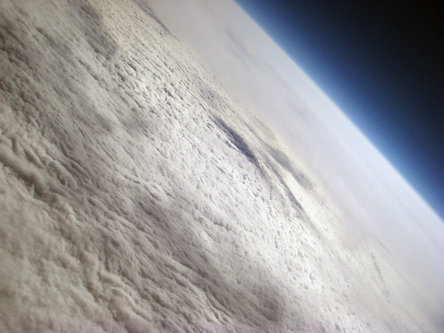
Link: High altitude still pictures (60000 ft up)

jcoxon77's photostream, Flicr:
http://www.flickr.com/photos/jcoxon77/
They look pretty cool, don't they?
But 76500 ft looks even cooler:

http://www.flickr.com/photos/nebarnix/sets/72157607393699828/
Interestingly though, 42000 ft still looks pretty amazing:
Will it blend?

Seems like, yes it did :)


Created with the latest iRhino alpha.
Changes:
* Placeholder engine nacelles added.
* Rudder added
I was reading today the book "Fluid dynamic drag" a bit and got kind of inspired: canopies and wind shield discontinuity contributes very much to the drag coefficient of the fuselage. Not only the laminar nose seems important, but all kinds of places where something ends and something else continues are sources of waste of engery.
So if the plane is completely faired with no discontinuity of any kind, theoretically the drag coefficient should be very low.
In this picture, the engine nacelle placeholders are just placeholders, because they are not yet accurate airfoil, and it has not been taken into account that in Rotax engines the propeller shaft is not in the middle of the engine, but almost on the top of the engine, this creates a fairing that has the lower side turned up a bit and is therefore not completely symmetrical.
The engine nacelles may need to be moved outwards, otherwise there is not enough clearance between the fuselage and the propeller arc.
I was also reading one day some NASA tech paper about wing tip mounted propellers. I have not drawn such things to this picture, but I may add it later - small brushless DC motor on each wing tip lowers the induced drag quite a bit according to the tech paper (although on high aspect ratio wing the effect is not that radical as on with a low aspect ratio wing that would otherwise be poor).
Potential issues for placing engine nacelles on wings (which seems pretty necessary for a twin, after all, may be the least bad compromise) and blending are the followings:
* the wings take a lot room to build (because they are very long)
* making the mold is difficult, because it has to be done from CNC cut pieces and glued together
* moving the center section to airport or transporting it in a container may be challenging, because if the area up to engine nacelles is continuous part of the center section and not separatable, it means that this is basically wider than the width of the container, shipping the plane to another continent might be a challenge (it seems that it would need to be flown like the design point has been set)

Wednesday, November 26, 2008
Three turbos in Subaru EJ22
Hey watch this out:
http://www.youtube.com/watch?v=bU2elPTJyqA
Pretty interesting system built around the Subaru.
http://www.youtube.com/watch?v=bU2elPTJyqA
Pretty interesting system built around the Subaru.
HALE
I have been thinking one idea for better utilizing the HALE concept (HALE = high altitude, long endurance).
Usually nobody flies higher than about 40000 ft. If you look out from a commercial passenger aircraft's window, what you see is blue. You can don't even see clouds very well since you are too high to see them closely and you are too low to see the curvature of the Earth and blackness of space. And the publicly available photography from that altitude is very limited, you don't really get to see even virtually how it looks like up there.
There are some interesting videos about balloon flights to high altitude in Youtube. The balloons go to about 80-100 kilofeets. According to videos, that looks already almost like space. Couple of examples:
Long Trail School High Altitude Balloon at Youtube
Nevada BalloonSat at Youtube
The view is so amazing that I feel it odd that nobody has started to carry people to near space experience with high altitude aircraft. Someone offers MIG-flights, but that is just a ballistic jump there from supersonic flight. Aircraft that can loiter in that altitude would give a whole different experience, it could stay there longer than just minutes.
That kind of aircraft would be impossible someone might say? Not so black and white. There are couple of HALE UAVs around which can go this high. And if you for example look Scaled Composites Proteus which can reach 70000 ft, if you'd replace the telecommunications load from the center section with space grade pressurized passenger cabin, the plane could lift several people at one time to the abovementioned altitude.
According to material I have been seeing from high altitude balloons, it seems like the sky is starting to look like space from about 60000 ft upwards. You need afterburning jet engines to go that high? Not necessarily. Look at for example Burt Rutan's UAV that had twin turbocharged modified Rotax 914 (with fuel injection). It was designed to have positive climb rate at 63000 ft. Seems feasible with piston engines in other words. The company that did the Rotax-conversion for the Scaled Composites UAV, have done triple turbocharged and twin turbocharged versions of the Rotax. The triple turbocharged Rotax is usable to over 80 kft, however, the installation looks really complicated (and the biggest turbo is so huge that must be from a truck).
Usually nobody flies higher than about 40000 ft. If you look out from a commercial passenger aircraft's window, what you see is blue. You can don't even see clouds very well since you are too high to see them closely and you are too low to see the curvature of the Earth and blackness of space. And the publicly available photography from that altitude is very limited, you don't really get to see even virtually how it looks like up there.
There are some interesting videos about balloon flights to high altitude in Youtube. The balloons go to about 80-100 kilofeets. According to videos, that looks already almost like space. Couple of examples:
Long Trail School High Altitude Balloon at Youtube
Nevada BalloonSat at Youtube
The view is so amazing that I feel it odd that nobody has started to carry people to near space experience with high altitude aircraft. Someone offers MIG-flights, but that is just a ballistic jump there from supersonic flight. Aircraft that can loiter in that altitude would give a whole different experience, it could stay there longer than just minutes.
That kind of aircraft would be impossible someone might say? Not so black and white. There are couple of HALE UAVs around which can go this high. And if you for example look Scaled Composites Proteus which can reach 70000 ft, if you'd replace the telecommunications load from the center section with space grade pressurized passenger cabin, the plane could lift several people at one time to the abovementioned altitude.
According to material I have been seeing from high altitude balloons, it seems like the sky is starting to look like space from about 60000 ft upwards. You need afterburning jet engines to go that high? Not necessarily. Look at for example Burt Rutan's UAV that had twin turbocharged modified Rotax 914 (with fuel injection). It was designed to have positive climb rate at 63000 ft. Seems feasible with piston engines in other words. The company that did the Rotax-conversion for the Scaled Composites UAV, have done triple turbocharged and twin turbocharged versions of the Rotax. The triple turbocharged Rotax is usable to over 80 kft, however, the installation looks really complicated (and the biggest turbo is so huge that must be from a truck).
Tecnam P2006T
Here is a design paper about Tecnam P2006T. I find it quite interesting.
www.aidaa.it/3-2008/P2006_corr.pdf
Interesting detail with the used Rotax 912S is that it provides actually better thrust at takeoff and climb than same horse power with a Lycoming engine (because the engine nacelle has smaller frontal area and the propeller rotation speed is lower).
www.aidaa.it/3-2008/P2006_corr.pdf
Interesting detail with the used Rotax 912S is that it provides actually better thrust at takeoff and climb than same horse power with a Lycoming engine (because the engine nacelle has smaller frontal area and the propeller rotation speed is lower).
Friday, November 21, 2008
New variant of the shape I have been thinking about
Here is my today's result from iRhino:

The idea is that the fuselage center section blends into wings like on blended wing body, but it only forms a minor portion of the shape, high aspect ratio wings continue from the blended part and there is a tail in the rear. I have not drawn this as I was thinking because I have been thinking either V-tail or T-tail. This picture doesn't yet have a rudder.
Now the difficulty is that I have hard time on getting the Rhino do what I think. The loft is challenging, because it follows airfoil shape, it follows the configuration and contour from the top I was thinking, but the problem is to vary the airfoil shape in the center section so that the transition from the right side to the left side is smooth and more circular than in this thing where it is pretty sharp (the sharpness there is completely unintentional and will go away as soon as I figure how to loft this thing properly).
The wing tips did not loft as I planned, and also the elevator has wrong airfoil shape in the tip, the scale2D produced results I was not planning to get. There is still something to learn in Rhino. I need to ask from maybe Jani tomorrow how to do this right.

The idea is that the fuselage center section blends into wings like on blended wing body, but it only forms a minor portion of the shape, high aspect ratio wings continue from the blended part and there is a tail in the rear. I have not drawn this as I was thinking because I have been thinking either V-tail or T-tail. This picture doesn't yet have a rudder.
Now the difficulty is that I have hard time on getting the Rhino do what I think. The loft is challenging, because it follows airfoil shape, it follows the configuration and contour from the top I was thinking, but the problem is to vary the airfoil shape in the center section so that the transition from the right side to the left side is smooth and more circular than in this thing where it is pretty sharp (the sharpness there is completely unintentional and will go away as soon as I figure how to loft this thing properly).
The wing tips did not loft as I planned, and also the elevator has wrong airfoil shape in the tip, the scale2D produced results I was not planning to get. There is still something to learn in Rhino. I need to ask from maybe Jani tomorrow how to do this right.
Monday, November 17, 2008
Attended on a composite fabrication course last weekend
I spent the weekend in Nummela. Jarmo Hakala was teaching composite fabrication there. We learned for example vacuum bagging and infusion molding techniques.
The infusion molding is surprisingly easy and doable. And it is not that expensive after all, all the materials needed (almost all) can be obtained from Etola. The only more expensive special thing wasted each time in the process is the sealing tape. That is available from the composite resellers only to my understanding (for example from Kevra in Finland). Of course the vacuum pump is needed and it needs to be very strong (not a lo-vac pump, but quite high vacuum to be powerful enough to make the resin to move in the molded part being wet out).
The infusion molding is especially handy when there are multiple layers on the part, and laying up them by hand would take lots of time. The infusion process is a lot more convenient, everything is placed when the part is dry etc. No sticky stuff involved. And everything happens by itself inside the bag. Biggest time goes to the preparation, e.g. making the bag completely sealed. It can not have any leaks, if it has, the part will fail.
I will try this out with the RC model(s) I am going to fabricate next. We have two vacuum pumps and one venturi tube (that creates vacuum from ordinary compressor) to try this out. Lets see how it works out at home. At the course it felt easy at least. With this process, providing that the bag is completely sealed and the resin is injected from proper places in, the quality of the end product can be very high, virtually almost eliminating sanding process.
The infusion molding is surprisingly easy and doable. And it is not that expensive after all, all the materials needed (almost all) can be obtained from Etola. The only more expensive special thing wasted each time in the process is the sealing tape. That is available from the composite resellers only to my understanding (for example from Kevra in Finland). Of course the vacuum pump is needed and it needs to be very strong (not a lo-vac pump, but quite high vacuum to be powerful enough to make the resin to move in the molded part being wet out).
The infusion molding is especially handy when there are multiple layers on the part, and laying up them by hand would take lots of time. The infusion process is a lot more convenient, everything is placed when the part is dry etc. No sticky stuff involved. And everything happens by itself inside the bag. Biggest time goes to the preparation, e.g. making the bag completely sealed. It can not have any leaks, if it has, the part will fail.
I will try this out with the RC model(s) I am going to fabricate next. We have two vacuum pumps and one venturi tube (that creates vacuum from ordinary compressor) to try this out. Lets see how it works out at home. At the course it felt easy at least. With this process, providing that the bag is completely sealed and the resin is injected from proper places in, the quality of the end product can be very high, virtually almost eliminating sanding process.
Friday, November 7, 2008
Scaled Raptor UAV Rotax 912 modification
I found an article about high altitude UAVs, and the Rotax 912 modification for Raptor UAV is mentioned here:
http://www.cre8tivenergy.com/uav.htm
(Quite interesting two stage turbo installation)
http://www.cre8tivenergy.com/uav.htm
(Quite interesting two stage turbo installation)
Tuesday, October 28, 2008
Progress on the manufacturing / process side development
As with the aerodynamics, I am also in a continuous learning mode with composite fabrication and also metalwork. We just purchased a TIG welding machine. That seems like a welding machine that have courage to try out, it is almost like using gas-welding but with a little arc. Hmm. like a little tesla-coil? How the arc behaves seems to be adjustable and e.g. it seems possible to avoid the crater when stopping weld by adjusting the time how long it takes for the arc to diminish. There are many adjustments in the machine and there is lot to learn. And we tried yesterday. Welding aluminum is tricky, it suddenly melts without prior warning. And even after that, it continues to melt more, if I didn't pay attention how long I heated it up. Anyway, seems like a fun challenge to master TIG-welding of aluminum. These things may be obvious for professional welders, but you know, they don't teach welding to engineers. One must start from somewhere. I will use the TIG-welding machine for construction of the big CNC machine that we have been planning with Kate for quite some time by now. A big CNC is needed for creating fuselage and wing plugs. Doing it inaccurately manually seems like great waste of time (have been trying and have found that it does not pay off, a better method is worth to be investigated - I don't take any "facts" for granted, unless I agree with the results and have compared the method to alternatives and found it to be the best for that purpose (by the way, different parts may require different kind of construction method, optimal is not always only one method)).
I have been researching also alternative materials since I obtained the Cozy MKIV plans (which I am not building right now). So I have pretty unused 20 kg can of MGS L285. Nothing wrong with the epoxy, but I just found out a better epoxy: The Hybtonite obviously - the carbon nanotube epoxy. The price seems competitive with the MGS (read: the MGS is overpriced because of shipping costs from Germany) and with about the same amount of money I could as well use this "breakthrough material". It does not change the world by itself, but it can add some welcome stiffness to pieces that might be otherwise too flexible. If I hadn't have this 20 kg unused can of MGS, I would be screaming and ordering a 20 kg can of Hybtonite right now. But having this unused epoxy in the garage a kind of slows the process down since I have lots of money invested in that can and the epoxy has limited shelf life. The Amroy representative is saying that the carbon nanotube material should be as safe as any other composite material (read: not more hazardous than epoxy is already, which is hazardous by definition).
I have been discussing off-line with one UAV/RC-plane designer. He has given me lots of valuable links. I may publish some of them sometime later on this blog, so stay tuned. I am not mentioning his name now, because I am not sure if he wants to be mentioned, but anyway, I find the information found this way quite interesting and helpful. As I have been reading these documents, it has also occurred to me sometimes, that what if the configuration layout would have looks and styling as one major parameter. In my opinion, B2 way the coolest publicly known aircraft out there. So I kind of love flying wings. But I have many reasons to not be thinking of designing a flying wing, for aerodynamic and stability standpoint. But one of the configurations (that I have known before of course, but these documents were kind of reminding me about those, that some find them actually useful over the conventional configuration) - the joint wing. What if you take a B2, use no twist - ie. make a normal main wing, and put a inverted V-tail into it in a box wing configuration so that the inverted V-tail starts from the wing tips, and it avoids yet another intersection by not connecting to the fuselage anywhere. This might make the controls a bit tricky, would mean wire in mechanical control rather than push-rods. Or maybe it could be a hybrid of fly-by-wire and manual control: aileron control could be manual and the elevator and rudder (and the mixing of the two) could be handled with electronics and servo motors would drive these surfaces. Would require very powerful servo motors though (needs to be very fast and very strong). But I have been sometimes kind of thinking this kind of fly-by-wire. Before someone screams that fly-by-wire takes hundreds of years to develop, I would like to remind that it is simple RC-plane technology that people are using all the time in the simplest form - fly-by-wire does not need to mean computerized flight controls and a aerodynamically unstable aircraft by definition. A electric wire weights less than a push-rod anyway when the length is very long (e.g. high aspect ratio wing, and in this case, something that starts from the wing tip). This configuration would make the cockpit very wide and not very tall. The looks would be compromised quite quickly if the cockpit part would protrude significantly from the wing. Obviously the cockpit section would be seamlessly blended into the wing. The interesting challenge here would be: how to make that work okay and minimize associated penalties rather than the motivation to choose this would be some parameter obtained from this configuration. At least it is that way until it is proven that this unorthodox configuration could be any good. At least it could be fun to make a RC-plane like that. And I would paint it to black. Full size plane would be trickier with the color, but there is high Tg Hybtonite available too. A realistic process could be infusion moulding with the hybtonite epoxy (I will investigate this at some point in the future, investing in process can pay back in construction phase significantly, instead of spending 20 years for sanding, I rather think first couple of years and try to optimize the actual construction work to not take 20 years). This would be a kind of alternative for carbon/glass prepregs.
I have been researching also alternative materials since I obtained the Cozy MKIV plans (which I am not building right now). So I have pretty unused 20 kg can of MGS L285. Nothing wrong with the epoxy, but I just found out a better epoxy: The Hybtonite obviously - the carbon nanotube epoxy. The price seems competitive with the MGS (read: the MGS is overpriced because of shipping costs from Germany) and with about the same amount of money I could as well use this "breakthrough material". It does not change the world by itself, but it can add some welcome stiffness to pieces that might be otherwise too flexible. If I hadn't have this 20 kg unused can of MGS, I would be screaming and ordering a 20 kg can of Hybtonite right now. But having this unused epoxy in the garage a kind of slows the process down since I have lots of money invested in that can and the epoxy has limited shelf life. The Amroy representative is saying that the carbon nanotube material should be as safe as any other composite material (read: not more hazardous than epoxy is already, which is hazardous by definition).
I have been discussing off-line with one UAV/RC-plane designer. He has given me lots of valuable links. I may publish some of them sometime later on this blog, so stay tuned. I am not mentioning his name now, because I am not sure if he wants to be mentioned, but anyway, I find the information found this way quite interesting and helpful. As I have been reading these documents, it has also occurred to me sometimes, that what if the configuration layout would have looks and styling as one major parameter. In my opinion, B2 way the coolest publicly known aircraft out there. So I kind of love flying wings. But I have many reasons to not be thinking of designing a flying wing, for aerodynamic and stability standpoint. But one of the configurations (that I have known before of course, but these documents were kind of reminding me about those, that some find them actually useful over the conventional configuration) - the joint wing. What if you take a B2, use no twist - ie. make a normal main wing, and put a inverted V-tail into it in a box wing configuration so that the inverted V-tail starts from the wing tips, and it avoids yet another intersection by not connecting to the fuselage anywhere. This might make the controls a bit tricky, would mean wire in mechanical control rather than push-rods. Or maybe it could be a hybrid of fly-by-wire and manual control: aileron control could be manual and the elevator and rudder (and the mixing of the two) could be handled with electronics and servo motors would drive these surfaces. Would require very powerful servo motors though (needs to be very fast and very strong). But I have been sometimes kind of thinking this kind of fly-by-wire. Before someone screams that fly-by-wire takes hundreds of years to develop, I would like to remind that it is simple RC-plane technology that people are using all the time in the simplest form - fly-by-wire does not need to mean computerized flight controls and a aerodynamically unstable aircraft by definition. A electric wire weights less than a push-rod anyway when the length is very long (e.g. high aspect ratio wing, and in this case, something that starts from the wing tip). This configuration would make the cockpit very wide and not very tall. The looks would be compromised quite quickly if the cockpit part would protrude significantly from the wing. Obviously the cockpit section would be seamlessly blended into the wing. The interesting challenge here would be: how to make that work okay and minimize associated penalties rather than the motivation to choose this would be some parameter obtained from this configuration. At least it is that way until it is proven that this unorthodox configuration could be any good. At least it could be fun to make a RC-plane like that. And I would paint it to black. Full size plane would be trickier with the color, but there is high Tg Hybtonite available too. A realistic process could be infusion moulding with the hybtonite epoxy (I will investigate this at some point in the future, investing in process can pay back in construction phase significantly, instead of spending 20 years for sanding, I rather think first couple of years and try to optimize the actual construction work to not take 20 years). This would be a kind of alternative for carbon/glass prepregs.
Monday, October 27, 2008
Xfoil for Ubuntu Intrepid
You may find out that Xfoil is not in the Ubuntu repositories. For compiling the source package, you need g77 compiler, but that is not included to Ubuntu Intrepid repositories right now and getting it to work from the source seems to be a lot of trouble. Here is what I found, after some digging, a ready made package which installed on Ubuntu Intrepid fine:
http://giuschet.altervista.org/Ubuntu/
Download the file and install with
sudo dpkg -i xfoil_6.97-1_i386.deb
If some of the dependending libraries are missing, just install those from Intrepid repository and it works fine without problems. Have fun!
For more reading about XFoil, please see:
Xfoil manual
Xfoil tutorial with illustrations
Terrabreak.org XFoil tutorial
More on Xfoil at mh-aerotools
http://giuschet.altervista.org/Ubuntu/
Download the file and install with
sudo dpkg -i xfoil_6.97-1_i386.deb
If some of the dependending libraries are missing, just install those from Intrepid repository and it works fine without problems. Have fun!
For more reading about XFoil, please see:
Xfoil manual
Xfoil tutorial with illustrations
Terrabreak.org XFoil tutorial
More on Xfoil at mh-aerotools
Sunday, October 26, 2008
Fuselage cross sections with iRhino
I described earlier on one blog entry how to make fuselage cross sections with iRhino easily. Here is the illustration of the lofted object cut to cross sections:
Cross sections, perspective:

Cross sections from front (simplified):

The source model:

The lofting capabilities of iRhino are awesome, it is easy to create shapes that would be impossible to come up with 2D cad models. I continue to be amazed with the quality of Rhino and I am also more and more convinced that there is no need for a 2D drawing program, I can do everything with Rhino. We are going to model our house next (which will not be discussed on this blog because it is not on-topic), while it is excellent for uniform 3D-shapes, it works so nicely with 2D shapes as well that it would be quite lame to spend all the time for nothing with AutoCAD (I am still getting shivers about the bad user interface, how simple things could take enormous amount of time to do and how innovation could get killed by the tool, we used to use that program when I was doing my studies, it is like completely from different planet than Rhino, and it is not a compliment for AutoCAD) where the work can be completed in matter of minutes in the Rhino..
Cross sections, perspective:

Cross sections from front (simplified):

The source model:

The lofting capabilities of iRhino are awesome, it is easy to create shapes that would be impossible to come up with 2D cad models. I continue to be amazed with the quality of Rhino and I am also more and more convinced that there is no need for a 2D drawing program, I can do everything with Rhino. We are going to model our house next (which will not be discussed on this blog because it is not on-topic), while it is excellent for uniform 3D-shapes, it works so nicely with 2D shapes as well that it would be quite lame to spend all the time for nothing with AutoCAD (I am still getting shivers about the bad user interface, how simple things could take enormous amount of time to do and how innovation could get killed by the tool, we used to use that program when I was doing my studies, it is like completely from different planet than Rhino, and it is not a compliment for AutoCAD) where the work can be completed in matter of minutes in the Rhino..
Thursday, October 23, 2008
Feasibility of air travel on short distances
I, like many others, have been thinking the state of the current air travel system. With all the security checks and check-ins, the travel time becomes long. And easily using car, train or bus wins the passenger plane in the spent time for traveling from place A to B.
In other words, if you fly from Helsinki to Tampere, you can expect the check-in etc. to take at least 1.5 hours prior to the flight and then the flight takes maybe 0.5 hours. It might be also late, cancelled etc., and if this is a connecting flight, you may need to wait for your flight for another 5 hours sitting at the airport. On the other side you are waiting for your luggage to come, and it may take easily 0.5 hours.
So the shortest time with check-in luggage to travel from Helsinki to Tampere is maybe 1.5+0.5+0.5 hours = 2.5 hours. You may have also spent 60-70 euros for taxi from home to the airport, and on the other side the same amount of money to taxi. This makes moving from Helsinki to Tampere to be 180/2.5 = 72 km/h.
What about if this was a connecting flight that you waited for 5 hours and which was one hour late. That makes 5+1+0.5+0.5 = 7 hours. This makes the speed 180/7.0 = 25 km/h. You could beat the plane with a bicycle!
How about if you used a light aircraft to fly by yourself:
- Getting to the airport takes the same time, although it is easier to get to the Malmi airport than to Helsinki-Vantaa with public transportation without paying the large Taxi fee.
- Doing pre-flight check for the plane takes 0.5 hours. If you are quick, you have filed flight plan etc. during this time too. You may be able to speed this up if you are not flying alone.
- If the plane flies 222 km/h on average (includes takeoff and landing), taxi tie down etc. time is accounted with +0.5 hours (includes both airports), the total time to fly to Tampere would be: 0.5 + 0.5 + 180/222.0 = 1.81 hours. This is 99 km/h.
So the slow light general aviation plane is faster than the airliner on this trip. It doesn't win use of car though, getting to the airport and from the another airport takes time. But it wins train, because in case of train, you would have to get to the train station, and get from the train station to your destination with public transportation, which adds easily 0.5 hours on both ends, even Pendolino is therefore slower than the private car on this distance, so it is not better than using the personal aircraft.
How about if the light plane was a bit faster. It would travel 300 km/h. The travel time would become 1.6 hours. This is 112.5 km/h. Actually you can save fuel on Toyota Prius if you travel 112.5 km/h. And you are sooner directly at your destination. Not bad though for the plane. Wins the airliner hands down even in the best case.
If the distance was a bit longer, it would change the other way. The private plane would be a lot faster way to travel than car. And the airline would still have the overhead associated with security checks, package check-ins, package claims etc. For example, already if you would be going to Kuopio or Jyväskylä, the personal aircraft would be faster than the private car. And still the airliner would be the loser in the speed.
If you would go to e.g. Tallinn, Estonia, then the private plane would be excellent choice. That is because you can't go there by car, you have to use some transportation in between (e.g. boat). Even fastest boats are slow compared to even small ultralight aircraft. You could take the airliner, but it would take very long to get to the destination because of the overhead taking place at the airport. Instead if you took off with private plane, the overhead can be made smaller.
This of course requires that the plane could be flown in all weather and it would be simple to operate, with no need to do complicated tasks prior to flight in the pre-flight check. Something that would be for personal travel like a family car rather than for "flying sport". And the plane should be very low drag and very high efficiency design to make it compete in the fuel burn with the car (competing with e.g. Toyota Prius with a plane is very tough - the fuel budget for 100 km would be about 5 liters to be equal). Many current aircraft are not like that. But I feel that there would be use for that kind of planes, and this would not be impossible.
Here is by the way a video I recorded last May in the California trip. This video is about flight from Mojave Space Port to Palo Alto.
Cirrus SR20 flight from Mojave to Palo Alto (raw footage) from Karoliina Salminen on Vimeo.
In other words, if you fly from Helsinki to Tampere, you can expect the check-in etc. to take at least 1.5 hours prior to the flight and then the flight takes maybe 0.5 hours. It might be also late, cancelled etc., and if this is a connecting flight, you may need to wait for your flight for another 5 hours sitting at the airport. On the other side you are waiting for your luggage to come, and it may take easily 0.5 hours.
So the shortest time with check-in luggage to travel from Helsinki to Tampere is maybe 1.5+0.5+0.5 hours = 2.5 hours. You may have also spent 60-70 euros for taxi from home to the airport, and on the other side the same amount of money to taxi. This makes moving from Helsinki to Tampere to be 180/2.5 = 72 km/h.
What about if this was a connecting flight that you waited for 5 hours and which was one hour late. That makes 5+1+0.5+0.5 = 7 hours. This makes the speed 180/7.0 = 25 km/h. You could beat the plane with a bicycle!
How about if you used a light aircraft to fly by yourself:
- Getting to the airport takes the same time, although it is easier to get to the Malmi airport than to Helsinki-Vantaa with public transportation without paying the large Taxi fee.
- Doing pre-flight check for the plane takes 0.5 hours. If you are quick, you have filed flight plan etc. during this time too. You may be able to speed this up if you are not flying alone.
- If the plane flies 222 km/h on average (includes takeoff and landing), taxi tie down etc. time is accounted with +0.5 hours (includes both airports), the total time to fly to Tampere would be: 0.5 + 0.5 + 180/222.0 = 1.81 hours. This is 99 km/h.
So the slow light general aviation plane is faster than the airliner on this trip. It doesn't win use of car though, getting to the airport and from the another airport takes time. But it wins train, because in case of train, you would have to get to the train station, and get from the train station to your destination with public transportation, which adds easily 0.5 hours on both ends, even Pendolino is therefore slower than the private car on this distance, so it is not better than using the personal aircraft.
How about if the light plane was a bit faster. It would travel 300 km/h. The travel time would become 1.6 hours. This is 112.5 km/h. Actually you can save fuel on Toyota Prius if you travel 112.5 km/h. And you are sooner directly at your destination. Not bad though for the plane. Wins the airliner hands down even in the best case.
If the distance was a bit longer, it would change the other way. The private plane would be a lot faster way to travel than car. And the airline would still have the overhead associated with security checks, package check-ins, package claims etc. For example, already if you would be going to Kuopio or Jyväskylä, the personal aircraft would be faster than the private car. And still the airliner would be the loser in the speed.
If you would go to e.g. Tallinn, Estonia, then the private plane would be excellent choice. That is because you can't go there by car, you have to use some transportation in between (e.g. boat). Even fastest boats are slow compared to even small ultralight aircraft. You could take the airliner, but it would take very long to get to the destination because of the overhead taking place at the airport. Instead if you took off with private plane, the overhead can be made smaller.
This of course requires that the plane could be flown in all weather and it would be simple to operate, with no need to do complicated tasks prior to flight in the pre-flight check. Something that would be for personal travel like a family car rather than for "flying sport". And the plane should be very low drag and very high efficiency design to make it compete in the fuel burn with the car (competing with e.g. Toyota Prius with a plane is very tough - the fuel budget for 100 km would be about 5 liters to be equal). Many current aircraft are not like that. But I feel that there would be use for that kind of planes, and this would not be impossible.
Here is by the way a video I recorded last May in the California trip. This video is about flight from Mojave Space Port to Palo Alto.
Cirrus SR20 flight from Mojave to Palo Alto (raw footage) from Karoliina Salminen on Vimeo.
Tuesday, October 21, 2008
Eclipse ECJ
Here is Gizmag's article about Eclipse EJC:
http://www.gizmag.com/go/7668/
Pictures on Airliners.net:
Airliners.net: Eclipse ECJ
http://www.gizmag.com/go/7668/
Pictures on Airliners.net:
Airliners.net: Eclipse ECJ
Saturday, October 18, 2008
Suction stabilization for low fineness ratio pusher engine pod
I got an idea how to achieve suction to the read of the engine pod.
* The prop is located just after the laminar-turbulent transition to the pod and the remainings of the pod is a very large spinner which is open from the center.
* The air tunnel inside the pod has venturi-shape.
* There are tunnels that connect the venturi tube and the ring that is supposed to have suction.
* Airflow (which is used to engine cooling) inside the venturi (helped with the propeller part that is inside the pod) causes suction to the rear of the pod. The air exits at the end of the venturi tube, which happens to be the center of the spinner.
* The exhaust in the center makes the cut aft end of the spinner to still maintain low drag, it functions in the same way as the rear cut fuselages in jets
I have not tested this idea and don't know it it would work, but I think it would be pretty easy to try out in the model scale, even with an electric motor. This interests me enough that I think I am going to try it out of someone doesn't tell me (with better knowledge, as a fact that has been proven and tested) that it is not gonna work.
I hereby license this invention under the terms and conditions of GNU General Public License, version 3, or any later version. (C) 2008 Karoliina Salminen. All rights reserved. By reading this text, you aknowledge this and agree with the terms and conditions of the GPL license.
* The prop is located just after the laminar-turbulent transition to the pod and the remainings of the pod is a very large spinner which is open from the center.
* The air tunnel inside the pod has venturi-shape.
* There are tunnels that connect the venturi tube and the ring that is supposed to have suction.
* Airflow (which is used to engine cooling) inside the venturi (helped with the propeller part that is inside the pod) causes suction to the rear of the pod. The air exits at the end of the venturi tube, which happens to be the center of the spinner.
* The exhaust in the center makes the cut aft end of the spinner to still maintain low drag, it functions in the same way as the rear cut fuselages in jets
I have not tested this idea and don't know it it would work, but I think it would be pretty easy to try out in the model scale, even with an electric motor. This interests me enough that I think I am going to try it out of someone doesn't tell me (with better knowledge, as a fact that has been proven and tested) that it is not gonna work.
I hereby license this invention under the terms and conditions of GNU General Public License, version 3, or any later version. (C) 2008 Karoliina Salminen. All rights reserved. By reading this text, you aknowledge this and agree with the terms and conditions of the GPL license.
Friday, October 17, 2008
iRhino learnings of Today
Today a colleague (Jani Ylinen, a graphics designer who knows everything about Rhino and Maya) from Nokia helped me out with Rhino a bit. So here is what I learned today.
If there is need to make 2D cross sections of for example of the fuselage, it can be done as follows:
1. Create a rectangular surface.
2. Make rectangular array of it. Adjust proper step to proper direction and use appropriate number of copies. E.g. 100 cross sections, one per each 5 cm for example.
3. Then choose Object intersection. Select all items (the rectangles plus the 3D model that you are going to cut apart)
4. Hit enter and wait that iRhino does the processing. It is slow in the current alpha-version.
5. Move the cross sections to another layer
6. Hide the 3D object layer
7. And you have cross sections. You can export these to in dxf format to for example to Qcad and process them further there. E.g. you can plot them to paper. Printing from Rhino is possible as well, but it prints the zoom level of a view that is currently present, and the scale you get can be about anything (not something that you can repeat for each model and do exactly the same scale drawings on paper each time, does not succeed with Rhino printing capabilities).
Jani also showed how to do radius. Select radius tool, select surfaces and type the radius and hit enter. Magically the radius appears to the piece with amazing accuracy.
There is also a silhouette function that makes a 2D projection out of the wireframe. You can propably utilize that in a 2D Cad, e.g. QCad (or Autocad if you are wealthy enough to have the overpriced licence to that outdated software).
I learned today that actually Rhino can be used for technical drawing without using more traditional technical drawing programs. You need to keep your model history with layers manually (if you change some cross section for example, you need to loft again), but with some work, it seems to be all you need. Also measurements can be handled, but you need to maintain them manually too, if you change some shape, you may need to update your dimension as well. With cutaways with the cross sections and the silhouette function, it seems that all sorts of technical drawing can be done with Rhino. It is different and some things are very manual, but on the other hand, as a bonus, the 3D side is so blazingly good that there is nothing that compares with it in user friendliness and expressivity. You can really create with this tool and about everything is there, you just need to discover all the functions.
Seems like the price-value ratio of Rhino is exceptionally good. With one thousand you can get so nice tool that it actually is better and especially a lot easier to use than overpriced Autodesk tools. This is how the design is done in the future for sure.
I am also downloading the Maya personal edition for Mac now. I plan to try it out for rendering models modeled in iRhino.
Many thanks to Jani for guidance with graphics software. It is very much fun to learn new things.
If there is need to make 2D cross sections of for example of the fuselage, it can be done as follows:
1. Create a rectangular surface.
2. Make rectangular array of it. Adjust proper step to proper direction and use appropriate number of copies. E.g. 100 cross sections, one per each 5 cm for example.
3. Then choose Object intersection. Select all items (the rectangles plus the 3D model that you are going to cut apart)
4. Hit enter and wait that iRhino does the processing. It is slow in the current alpha-version.
5. Move the cross sections to another layer
6. Hide the 3D object layer
7. And you have cross sections. You can export these to in dxf format to for example to Qcad and process them further there. E.g. you can plot them to paper. Printing from Rhino is possible as well, but it prints the zoom level of a view that is currently present, and the scale you get can be about anything (not something that you can repeat for each model and do exactly the same scale drawings on paper each time, does not succeed with Rhino printing capabilities).
Jani also showed how to do radius. Select radius tool, select surfaces and type the radius and hit enter. Magically the radius appears to the piece with amazing accuracy.
There is also a silhouette function that makes a 2D projection out of the wireframe. You can propably utilize that in a 2D Cad, e.g. QCad (or Autocad if you are wealthy enough to have the overpriced licence to that outdated software).
I learned today that actually Rhino can be used for technical drawing without using more traditional technical drawing programs. You need to keep your model history with layers manually (if you change some cross section for example, you need to loft again), but with some work, it seems to be all you need. Also measurements can be handled, but you need to maintain them manually too, if you change some shape, you may need to update your dimension as well. With cutaways with the cross sections and the silhouette function, it seems that all sorts of technical drawing can be done with Rhino. It is different and some things are very manual, but on the other hand, as a bonus, the 3D side is so blazingly good that there is nothing that compares with it in user friendliness and expressivity. You can really create with this tool and about everything is there, you just need to discover all the functions.
Seems like the price-value ratio of Rhino is exceptionally good. With one thousand you can get so nice tool that it actually is better and especially a lot easier to use than overpriced Autodesk tools. This is how the design is done in the future for sure.
I am also downloading the Maya personal edition for Mac now. I plan to try it out for rendering models modeled in iRhino.
Many thanks to Jani for guidance with graphics software. It is very much fun to learn new things.
RC Advisor
Carlos from RCAdvisor commented my one post and I decided to check out his site. I created user account there etc. I was really amazed the RC Calculator, it not only has quite amazing features for model makers, but it also seems to have quite interesting animated UI, I didn't know that this kind of stuff can be nowadays done with Java (or is it flash?). I haven't had time to yet surf what all is on this site, but it looks quite comprehensive and promising and I will for sure look further into it. Indeed, maybe I find some tips for the twin concept RC-scale model I am going to do. Thanks Carlos for your link!
the link to the RCAdvisor
the link to the RCAdvisor
Thursday, October 16, 2008
Trying out different configuration layout for the twin concept

I decided to post here a snapshot of one of my Rhino-models. It has now struts which hold the engines out of the wing surface. The canopy was also replaced with windows.


Monday, October 13, 2008
Modern and even future concepts from over 70 years ago
There are interesting similarities in the old Luftwaffe aircraft concepts to the modern aircraft flying now:
For example:
Similar to Rutan Boomerang
Similar to Adam A700 (Originally designed by Burt Rutan)
Similar to NASA Oblique wing (which was by the way done by Scaled Composites / Burt Rutan)
Almost like the Rutan SpaceShipOne
Some features of Rutan WhiteKnight 1
Wing dihedral and anhedral similar to Rutan Proteus
From up, this could be mistaken to Rutan Long-Ez
Hey I can find similarities to Rutan Vari-Viggen here
Here is the WhiteKnight 2 configuration obviously
Almost like Adam A500 (originally designed by Burt Rutan)
Ok, then what about these:
RAM-jet, back in 1946
First commercial jet aircraft was DeHaviland Comet. But was it invented there? Doesn't this have quite recognizable look. The airliners still have this configuration and look.
And finally, but not least, this one:
Governments are still flying people into orbit with less modern hardware than this, and the idea to this one was from 1929 originally!. Think of it - first flights to space were super-ancient designs (non-aerodynamic rockets) instead of what was thought tens of years earlier already. Even Space Shuttle is quite clumsy compared to what this could have been. I would not be surprised to see someday a rendering on a page of a science magazine, which would look exactly like this and have for example the Northrop-Grumman -logo on it. The sad part was that this was only considered as a bomber, everything was some sort of warplane, it somehow didn't occur to people back then that they could have done the first human space flight earlier than it was done. I wonder why wasn't Dr. Säger utilized in the space programs which followed couple of tens of years later. I am thinking what could be done if the rocket monorail-train was replaced with a MAGLEV-train (and the track would slope upwards inside a mountain to the altitude of couple of kilometers in a tunnel). Wow. If my hair was short, it would be most likely pointing to the ceiling now.
Seems like to design a novel plane, there are examples of about every possible configuration layout, which have been long forgotten already and nobody has maybe utilized it, it just is waiting for someone to find it. The history of unfinished aircraft concepts seems to be an interesting source for inspiration.
So, if there could have been a orbital space plane already in 1930s or so, and ramjets were thought about already back in the 1940s, how much then air travel has advanced in something like 70 years? Not at all, it seems. With modern materials and tools, the feasibility of these designs have increased, but the idea still is very old. And most modern designs are just copies of each other without anything new and creative.
For example:
Similar to Rutan Boomerang
Similar to Adam A700 (Originally designed by Burt Rutan)
Similar to NASA Oblique wing (which was by the way done by Scaled Composites / Burt Rutan)
Almost like the Rutan SpaceShipOne
Some features of Rutan WhiteKnight 1
Wing dihedral and anhedral similar to Rutan Proteus
From up, this could be mistaken to Rutan Long-Ez
Hey I can find similarities to Rutan Vari-Viggen here
Here is the WhiteKnight 2 configuration obviously
Almost like Adam A500 (originally designed by Burt Rutan)
Ok, then what about these:
RAM-jet, back in 1946
First commercial jet aircraft was DeHaviland Comet. But was it invented there? Doesn't this have quite recognizable look. The airliners still have this configuration and look.
And finally, but not least, this one:
Governments are still flying people into orbit with less modern hardware than this, and the idea to this one was from 1929 originally!. Think of it - first flights to space were super-ancient designs (non-aerodynamic rockets) instead of what was thought tens of years earlier already. Even Space Shuttle is quite clumsy compared to what this could have been. I would not be surprised to see someday a rendering on a page of a science magazine, which would look exactly like this and have for example the Northrop-Grumman -logo on it. The sad part was that this was only considered as a bomber, everything was some sort of warplane, it somehow didn't occur to people back then that they could have done the first human space flight earlier than it was done. I wonder why wasn't Dr. Säger utilized in the space programs which followed couple of tens of years later. I am thinking what could be done if the rocket monorail-train was replaced with a MAGLEV-train (and the track would slope upwards inside a mountain to the altitude of couple of kilometers in a tunnel). Wow. If my hair was short, it would be most likely pointing to the ceiling now.
Seems like to design a novel plane, there are examples of about every possible configuration layout, which have been long forgotten already and nobody has maybe utilized it, it just is waiting for someone to find it. The history of unfinished aircraft concepts seems to be an interesting source for inspiration.
So, if there could have been a orbital space plane already in 1930s or so, and ramjets were thought about already back in the 1940s, how much then air travel has advanced in something like 70 years? Not at all, it seems. With modern materials and tools, the feasibility of these designs have increased, but the idea still is very old. And most modern designs are just copies of each other without anything new and creative.
Wednesday, October 8, 2008
Wing droops on laminar flow section
If you have wondered why Cirrus has the discontinuity on the wings. This may answer to that to some extent. I have not found any factual information about the airfoil section used on the Cirrus other than that it is a natural laminar flow section. Cirrus VK-30 used the Jeff Viken NLF414F airfoil. I don't know if the SR20/SR22 uses the same airfoil or a different NLF section.
Anyway in this NASA tech paper it is explained how the stall resistance can be made better with the wing droop. The wing droop on the NASA test C210 actually indeed resembles the discontinuity on the Cirrus SR20/SR22 wing. Please have a look:
Wind tunnel results of the low-speed NLF(1)-0414F airfoil
Notable thing is that the Vmax-probe did not have this wing droop or any other means to prevent tip stall. And it crashed on landing possibly according to NTSB report and Bruce Carmichael's book, because of unfavorable stalling charasteristics at low Re of the airfoil caused a hard landing (which the pilot did not survive). NLF414F is not to be used without some means to prevent tip stall and to soften the otherwise very sharp stall at low Re.
Anyway in this NASA tech paper it is explained how the stall resistance can be made better with the wing droop. The wing droop on the NASA test C210 actually indeed resembles the discontinuity on the Cirrus SR20/SR22 wing. Please have a look:
Wind tunnel results of the low-speed NLF(1)-0414F airfoil
Notable thing is that the Vmax-probe did not have this wing droop or any other means to prevent tip stall. And it crashed on landing possibly according to NTSB report and Bruce Carmichael's book, because of unfavorable stalling charasteristics at low Re of the airfoil caused a hard landing (which the pilot did not survive). NLF414F is not to be used without some means to prevent tip stall and to soften the otherwise very sharp stall at low Re.
Tuesday, October 7, 2008
Pressure thrust and plasma drag reduction patent links
I find this quite interesting:
http://www.wipo.int/pctdb/en/wo.jsp?IA=US2005047133&wo=2006073954&DISPLAY=DESC
Here is another:
Plasma drag reduction
http://www.wipo.int/pctdb/en/wo.jsp?IA=US2005047133&wo=2006073954&DISPLAY=DESC
Here is another:
Plasma drag reduction
Monday, October 6, 2008
Conceptual design, design requirements, high efficiency twin
Here are set of requirements I have combined for an aircraft suitable for my use case. I have been collecting these things for quite long time now, and have changed them back and forth. However, it seems like they are becoming more stable now:
- Two engines. Rotax 914 (preferably fuel injected) or similar (912 turbo conversion). Alternate engines: HKS700T (the speed may not be achieved with the HKS option). (low power engines which run on autogas are mandatory requirement)
- Range 1000 nm with three on board (mandatory requirement)
- at least 3 places (mandatory requirement, long range flights, third seat is needed for baggage and rescue equipment)
- Designed for IFR flying (mandatory requirement)
- statically stable, dynamically stable behavior (mandatory requirement)
- gentle stall (mandatory requirement (for safety))
- Cruise speed > 200 kts @ 80% power (mandatory requirement for both range and usefulness)
- Stall speed max 55 kts (mandatory requirement, for safety)
- High altitude capable (cruise at 24000 feet) (optional requirement)
- Pressurization as an option (optional requirement)
- Lightning strike protection (mandatory requirement)
- Positive climb rate with one engine out (mandatory requirement)
- Spin recovery possible (mandatory requirement)
- Very high glide ratio and long glide range when both engines out (mandatory requirement)
- BRS system (mandatory requirement, for safety)
- Spin recovery parachute (mandatory requirement, for testing safety)
- Tri-gear possibly with RG, at least the nosegear with RG mechanism (Trigear mandatory, RG optional)
- At least normal category (mandatory requirement)
- Utility category (optional requirement)
- Reasonable cost to build a prototype
Means how to achieve this:
- Selection of efficient NLF airfoils
- By minimizing fuselage and engine pod wetted area
- By minimizing skin friction drag (smooth surface, gelcoat on top of laminate and polyurethane paint on top of gelcoat)
- By utilizing laminar flow over wings and fuselage as much as possible
- By using wing geometry that has higher effective aspect ratio than actual AR
- Turbocharged engines
- Lightweight molded composite structure manufactured from carbon fiber prepregs, foam.
- By minimizing intersections and protruding elements. As clean fuselage and wing as possible. Known limitations - double slotted flaps do require external mechanism.
- By use of double slotted flaps for high Clmax.
- By use of either T-tail or V-tail for good spin recovery.
- Large fuel tanks in engine pods
- For cost effectivity, a pair of midtime Rotax 912ULs equipped with e.g. VEMS fuel injection and Garrett turbocharger is more reasonable cost than pair of stock Rotax 914s. Downside: ease of installation is lost when the engine requires more work than usual for Rotax installations. However, fuel injection is essential for safety.
- Negative sweep on main wings
- Glass cockpit (IFR requirement)
Possible configurations to achieve this:
- Twin with tractor propellers on each wing (known limitation: the propeller causes turbulent flow behind it which increases drag over the engine pod and the wing behind the propeller arc)
- Twin with pusher propellers on each wing (known limitation: the pod on front of propeller decreases the propeller efficiency)
- Push-pull configuration with twin boom tail (known limitation: front propeller disturbs the airflow to the rear propeller and the efficiency of the rear propeller decreases)
How to verify the effectiveness of each parameter:
- Calculate basic parameters for each combination where only one parameter is altered in each.
- This concept generates several different designs and each parameter is justified if it produces verifiable benefit.
- The design points that are proven to produce positive results with large enough margin are incorporated into the design if it does not overly complicate the manufacturing.
Low hanging fruits (design points known to have been succesfull in other designs):
- Double slotted flaps with a mechanism similar to Dynaero. Proven on Dynaero MCR.
- NLF-airfoils. Proven on Cirrus, Lancair and Columbia (Cessna 350 and Cessna 400 nowadays) high performance aircraft.
- Molded composite structures. Industry standard nowadays in most new aircraft designs.
- Tractor twin. Proven on most twins around.
- Pusher twin. Proven on a Polish design called Orca.
- V-tail. Proven on Beech Bonanza and later Cirrus Jet and Eclipse Jet.
- T-tail. Proven on many aircraft designs to date
- High aspect ratio on twin engine propeller driven aircraft. Proven on Diamond DA42.
- Negative sweep (moderate) found on many dual seat gliders. Small amount of negative sweep can also be found from Diamond aircraft.
- Trapezoid on wings. Easy to manufacture from composite materials, the shape is not limited by manufacturing process.
- Prepreg composites. Proven on Cirrus, Lancair, Diamond and Columbia aircraft.
- Rotax 912 series engines. Proven to be highly reliable and simple workhorse on almost all new ultralight and LSA aircraft. HKS is slowly gaining some share, but Rotax rules so far. From personal experience I also know that the Rotax engines meet their TBO, our flying club frequently runs Rotax engines to their TBO without problem without major overhauls. Claims that TBO of Rotax is just marketing and that overhaul is required well before 1000 hours to that is simply not true, this has been proven by experience, the aircraft we used to own has flown about 1000 hours, and the Rotax is the original one and runs nicely without problems and it has been in hard use because the plane was used for the first 683 hours to train student pilots. Rotax can also run on autogas (actually the preferred fuel is autogas, not 100LL).
- Glass cockpit can be made a lot simpler than tradtional gauges. Wiring behind traditional gauges is a mess and takes a lots of handwork to accomplish. Glass cockpit wiring can be made very simple and it can be highly integrated where most of the tasks are done in software rather than mechanics.
Criteria for defining success and failure
- Minimum acceptable range is 800 nm.
- Minimum acceptable payload with full fuel is three persons with no baggage.
- Minimum acceptable cruise speed at 80% is 160...170 kts on Rotax 912/100 hp. However, when comparing to Rotax 912 twins (coming and existing), the speed is no longer in the "top class", but rather below the top.
- Minimum acceptable glide ratio is 1:15. Target is more than that.
- Maximum acceptable stall speed is 55 kts. Design requires changes, if it is more than that.
- Two engines. Rotax 914 (preferably fuel injected) or similar (912 turbo conversion). Alternate engines: HKS700T (the speed may not be achieved with the HKS option). (low power engines which run on autogas are mandatory requirement)
- Range 1000 nm with three on board (mandatory requirement)
- at least 3 places (mandatory requirement, long range flights, third seat is needed for baggage and rescue equipment)
- Designed for IFR flying (mandatory requirement)
- statically stable, dynamically stable behavior (mandatory requirement)
- gentle stall (mandatory requirement (for safety))
- Cruise speed > 200 kts @ 80% power (mandatory requirement for both range and usefulness)
- Stall speed max 55 kts (mandatory requirement, for safety)
- High altitude capable (cruise at 24000 feet) (optional requirement)
- Pressurization as an option (optional requirement)
- Lightning strike protection (mandatory requirement)
- Positive climb rate with one engine out (mandatory requirement)
- Spin recovery possible (mandatory requirement)
- Very high glide ratio and long glide range when both engines out (mandatory requirement)
- BRS system (mandatory requirement, for safety)
- Spin recovery parachute (mandatory requirement, for testing safety)
- Tri-gear possibly with RG, at least the nosegear with RG mechanism (Trigear mandatory, RG optional)
- At least normal category (mandatory requirement)
- Utility category (optional requirement)
- Reasonable cost to build a prototype
Means how to achieve this:
- Selection of efficient NLF airfoils
- By minimizing fuselage and engine pod wetted area
- By minimizing skin friction drag (smooth surface, gelcoat on top of laminate and polyurethane paint on top of gelcoat)
- By utilizing laminar flow over wings and fuselage as much as possible
- By using wing geometry that has higher effective aspect ratio than actual AR
- Turbocharged engines
- Lightweight molded composite structure manufactured from carbon fiber prepregs, foam.
- By minimizing intersections and protruding elements. As clean fuselage and wing as possible. Known limitations - double slotted flaps do require external mechanism.
- By use of double slotted flaps for high Clmax.
- By use of either T-tail or V-tail for good spin recovery.
- Large fuel tanks in engine pods
- For cost effectivity, a pair of midtime Rotax 912ULs equipped with e.g. VEMS fuel injection and Garrett turbocharger is more reasonable cost than pair of stock Rotax 914s. Downside: ease of installation is lost when the engine requires more work than usual for Rotax installations. However, fuel injection is essential for safety.
- Negative sweep on main wings
- Glass cockpit (IFR requirement)
Possible configurations to achieve this:
- Twin with tractor propellers on each wing (known limitation: the propeller causes turbulent flow behind it which increases drag over the engine pod and the wing behind the propeller arc)
- Twin with pusher propellers on each wing (known limitation: the pod on front of propeller decreases the propeller efficiency)
- Push-pull configuration with twin boom tail (known limitation: front propeller disturbs the airflow to the rear propeller and the efficiency of the rear propeller decreases)
How to verify the effectiveness of each parameter:
- Calculate basic parameters for each combination where only one parameter is altered in each.
- This concept generates several different designs and each parameter is justified if it produces verifiable benefit.
- The design points that are proven to produce positive results with large enough margin are incorporated into the design if it does not overly complicate the manufacturing.
Low hanging fruits (design points known to have been succesfull in other designs):
- Double slotted flaps with a mechanism similar to Dynaero. Proven on Dynaero MCR.
- NLF-airfoils. Proven on Cirrus, Lancair and Columbia (Cessna 350 and Cessna 400 nowadays) high performance aircraft.
- Molded composite structures. Industry standard nowadays in most new aircraft designs.
- Tractor twin. Proven on most twins around.
- Pusher twin. Proven on a Polish design called Orca.
- V-tail. Proven on Beech Bonanza and later Cirrus Jet and Eclipse Jet.
- T-tail. Proven on many aircraft designs to date
- High aspect ratio on twin engine propeller driven aircraft. Proven on Diamond DA42.
- Negative sweep (moderate) found on many dual seat gliders. Small amount of negative sweep can also be found from Diamond aircraft.
- Trapezoid on wings. Easy to manufacture from composite materials, the shape is not limited by manufacturing process.
- Prepreg composites. Proven on Cirrus, Lancair, Diamond and Columbia aircraft.
- Rotax 912 series engines. Proven to be highly reliable and simple workhorse on almost all new ultralight and LSA aircraft. HKS is slowly gaining some share, but Rotax rules so far. From personal experience I also know that the Rotax engines meet their TBO, our flying club frequently runs Rotax engines to their TBO without problem without major overhauls. Claims that TBO of Rotax is just marketing and that overhaul is required well before 1000 hours to that is simply not true, this has been proven by experience, the aircraft we used to own has flown about 1000 hours, and the Rotax is the original one and runs nicely without problems and it has been in hard use because the plane was used for the first 683 hours to train student pilots. Rotax can also run on autogas (actually the preferred fuel is autogas, not 100LL).
- Glass cockpit can be made a lot simpler than tradtional gauges. Wiring behind traditional gauges is a mess and takes a lots of handwork to accomplish. Glass cockpit wiring can be made very simple and it can be highly integrated where most of the tasks are done in software rather than mechanics.
Criteria for defining success and failure
- Minimum acceptable range is 800 nm.
- Minimum acceptable payload with full fuel is three persons with no baggage.
- Minimum acceptable cruise speed at 80% is 160...170 kts on Rotax 912/100 hp. However, when comparing to Rotax 912 twins (coming and existing), the speed is no longer in the "top class", but rather below the top.
- Minimum acceptable glide ratio is 1:15. Target is more than that.
- Maximum acceptable stall speed is 55 kts. Design requires changes, if it is more than that.
Tuesday, September 30, 2008
Podrel
A funny idea came into my mind. There are couple of Petrel Amphibians in Finland. It looks like a plane of Donald Duck.
Here is one discussion thread in Finnish about it:
Nyt on suomen kolmas akuankkakone valmis
It has staggered wings (two wings, one on top of each other). What if it was completely different. Not exactly completely, but quite completely. Now on this latest Super Petrel, the engine pod is integrated to the upper wing. How if the upper wing was the only wing on the plane, the lower wing would not exist, the upper wing would be twice as long. The tail would not be angled upwards from the bottom of the fuselage, but it would be rather connected with two booms to the wing, in similar manner than it has been done on Adam A500. And finally, but not least, what if the fuselage was not a traditional fuselage, but a pod in the end of a strut, that fits the occupants, and nothing more. It would end before the prop arc. This would allow moving the propeller a bit downwards.
So the result:
- no aerodynamic penalty normally associated with the amphibian planes.
- center of thrust is at the same level as is the lift (high wing)
- because of the boom tail, the tail does not hit the water unless the plane flips.
- because you would not need to fit the tail to the fuselage, the fuselage-pod could be made a better boat shape
I could not resist, but name this idea as Podrel. Actually this is not a new idea entirely, it is partially borrowed from a NASA tech paper, but the application to amphibian use could be new twist for the configuration.
What do you think about this?
Here is one discussion thread in Finnish about it:
Nyt on suomen kolmas akuankkakone valmis
It has staggered wings (two wings, one on top of each other). What if it was completely different. Not exactly completely, but quite completely. Now on this latest Super Petrel, the engine pod is integrated to the upper wing. How if the upper wing was the only wing on the plane, the lower wing would not exist, the upper wing would be twice as long. The tail would not be angled upwards from the bottom of the fuselage, but it would be rather connected with two booms to the wing, in similar manner than it has been done on Adam A500. And finally, but not least, what if the fuselage was not a traditional fuselage, but a pod in the end of a strut, that fits the occupants, and nothing more. It would end before the prop arc. This would allow moving the propeller a bit downwards.
So the result:
- no aerodynamic penalty normally associated with the amphibian planes.
- center of thrust is at the same level as is the lift (high wing)
- because of the boom tail, the tail does not hit the water unless the plane flips.
- because you would not need to fit the tail to the fuselage, the fuselage-pod could be made a better boat shape
I could not resist, but name this idea as Podrel. Actually this is not a new idea entirely, it is partially borrowed from a NASA tech paper, but the application to amphibian use could be new twist for the configuration.
What do you think about this?
Dynaero MCR-01
I had a chance to see the Dynaero MCR-01 yesterday at Malmi airport. Here are some interesting pictures about it:
Front:

Dynaero smile:

Back:

Double slotted flaps:

Flap mechanism:

Canopy:

Interesting finding: the upper slot is rigid part of the flap. It does not move by itself, and the mechanism is as simple as on plain flap or the single slotted flap found on Cirrus or Diamond. When the flap is retracted, the slot hides under the wing. Very clever design.
Front:

Dynaero smile:

Back:

Double slotted flaps:

Flap mechanism:

Canopy:

Interesting finding: the upper slot is rigid part of the flap. It does not move by itself, and the mechanism is as simple as on plain flap or the single slotted flap found on Cirrus or Diamond. When the flap is retracted, the slot hides under the wing. Very clever design.
Subscribe to:
Posts (Atom)