I was just thinking about Curtis channel wing. I have a concern that this kind of design will result in tip stall in addition to the other problems there could be if something would fail.
However, what if you use electric motors instead and place that channel as a C on the tip of a wing? There is this 3D effect that flow tends to want to slip towards the tip and it causes wake turbulence and reduces Clmax. However, what if there is this C and then there is a prop inside the C. The flow comes to the prop and the prop sends it away and causes even bigger pressure differential between lower side of the wing and the upper side of the wing. With brushless DC electric motor it could be technically doable - one could not think about putting a Lycosaurus to the wing tip. You could even add redundancy by adding two motors in cascade. Should one fail, the another one would still be operational.
I think there are two kinds of aircraft that would be needed to cover the needs of personal air transportation: super stol/vtol for flying to airport from home to the pressurized long range plane that can cover large distances. I think today's general aviation falls in the middle of these, but I think it could be obsolete with these new two categories. I think the today's GA is not popular exactly because it falls between these two categories and does not fit in either purpose properly. And they are neither good toys nor good tools. This first VSTOL would cover the toy part and day to day short distance travel, and the HALE the serious transportation case.
I will write another blog entry about this split of concepts later because I believe I have - as a GA customer - found what's wrong with it. What are the needs and what is the gap. I think I have the answer.
Friday, July 15, 2011

Monday, May 30, 2011
Interesting post about Dynaero Clmax (>3.0) at HBA
These calculations might interest you if you are wondering what is the Clmax in those little aircraft. Rule of thumb from Daniel Raymer et all says it is impossible, but flight data from MCR proves that ULC R has nothing short of extraordinary high Clmax.
Read more here: http://www.homebuiltairplanes.com/forums/aircraft-design-aerodynamics-new-technology/10349-specifications-coefficient-lift-dyn-aero-lafayette-mcr-ban-bi.html
Read more here: http://www.homebuiltairplanes.com/forums/aircraft-design-aerodynamics-new-technology/10349-specifications-coefficient-lift-dyn-aero-lafayette-mcr-ban-bi.html
Friday, May 20, 2011
New renaissance for general aviation; what is needed and how that can be achieved
Lets face the facts: general aviation is starving. Or it could be said that general aviation is even dying. There are many signs to that: less and less people are getting pilot's license, regulations are becoming more and more unreasonable (especially in Europe for general aviation as they have been designed for airline companies, with all the standards drawn to such level where there is no business) and hardcore hobbyists (like myself) are flying with from aging and poor to mediocre flying machines that are very expensive to operate and that are not enough capable (there are few exceptions, but there would still be very much room for improvement) to be useful for serious transportation. Years come and go and nothing changes, and every new year comes with no progress and all new things come without learning anything new but rather on evolution which is not very steep but rather very shallow. Very small amount of people are interested anymore in subsonic flight and the breakthroughs needs to happen exactly on this subsonic flight this new renaissance to happen.
Yes, I am myself flying airplanes for fun, and the fun is very important. And the fun will need to remain important in the future as well. The fun part should therefore not be taken away. Airliners are taking the fun away, sitting in economy class is more like suffering than fun and business class is not fun either, everything has been made to take the attention away from the aviation, people are eating and drinking and not looking out of the window. Windows even are ridiculously small, even in business class.
Then if we look road transportation. How many people prefer traveling in bus rather than in a private car or taxi? Are you a bus-fan? At least I am not. We drive with our Prius to work everyday and my carbon emissions are less than they would be if we would drive with the 1/3 filled bus. You could argue that the bus drives anyway, but that is not the point. Bus travel is like being in the economy class, it does not have anything that I could describe with fun or enjoyable. However driving with own car or sitting in taxi can be much better experience.
So I think here is the cure for general aviation:
1) Diesel piston engine based efficient air taxis that can carry 5-6 persons. Requirement for the aircraft would be that they would need to be efficient (leading to low passenger mile cost), safe and comfortable. Low passenger mile cost means cost comparable to airline ticket price. This cost should be able to include the whole thing: aircraft cost, insurance, pilot, everything. I think this is doable, but requires some novel engineering and not doing things like they have been always done. These planes would look more like Burt Rutan's special machines with very long wings or they could be possibly also blended flying wings but one could not expect these to look like Cessna C150.
2) Personal aircraft (I am not repeating what cafe is saying about PAV, this is my personal view on this) intended for serious transportation with large level of automation. This calls for fly-by-wire and stability augmentation. Pilot would rather choose to which direction to drive rather than correcting for bumpy air or cross wind. It would be different from autopilot, you could still drive the plane, but the plane would make driving a lot more convenient and so much easier that most car drivers could learn it. There could be additional aids, such as landing aid which would automatically line up the plane with the runway. It could use machine vision to be able to help the landing path all the way to full stop on runway independently from navigation aids. It would be still fun to fly even if it would be much easier. Why the definition of fun has to be hard? These aircraft geared for personal transportation would be at least 4 place machines making them comparable to family car capability.
Lots of people are shouting that "more entry level planes are needed". I do not fully agree. There are lots of planes which are very suitable for flight training. For example the LSA planes, Diamonds, Cirruses etc. Of course if the intention was to fly a fly-by-wire PAV-machine, there could be a different path that would be trained with these PAV machines. Logical step in that direction would be to drop all medical, currency etc. requirements, but rather make the flying with these with similar requirements than driving a car. If flying these would be so easy, you simply would not need check rides now and then, BFRs etc. And then planes are made with unreliable parts which were certified 40 years ago while cars almost never break with parts that were designed one year ago.
In personal aircraft you fly with the computer the flying machine. This license should be upgradeable to a normal pilot's license which would require then learning to fly with planes with traditional controls and avionics. Some could argue that this would be so expensive as the computers would be so heavy and they would cost more than a plane and what not. I don't think so. Computer that can run this kind of algorithms in real time does not need to cost a fortune. In mass production, a reasonable price is hundreds of dollars, not tens of thousands or hundreds of thousands. Such computer weights less than 0.3 kg and while it would need some more weight for all the control hardware, it would not be that complicated. Actually telephones are so much more complicated today than any electronics in aircraft, in fact, these things are so low hanging fruits that they are waiting for somebody to implement.
What slows down the progress on this area in my opinion, is very conservative thinking in the aviation circles, not thinking out of the box and at least in Finland there seems to be a tendency to repeat old beliefs like they would be teachings in a church and even clever people may take silly things for granted. Of course that is all they can do, as there are no alternatives, but that does not mean it would be right. In fact, the situation with aviation is so desperate that this feels like some alternate universe in Stargate TV-series where things have gone real badly wrong. We are that dystopic parallel universe and someone needs to do something to fix it. So aviation in general needs a major overhaul. New kind of airplanes are needed, new kind of regulations are needed (while dropping old obsolete ones), new kind of air traffic control system is needed (when there are millions of personal planes in the air, there is no way for the current system to work, it is a dinosaur already, you can not have centralized system in a case where traffic is so huge, car traffic already has hard data about that) and new kind of attitudes are needed. New more efficient and less expensive mass produced planes and regulations are necessary enablers for the attitudes becoming more positive towards flying.
So what I am complaining about attitudes? Consider this: I was one day few years ago in cafeteria of the Malmi airport. There was a some mother with her child there. The little boy said that he wants to drive airplanes. The little boy spoke out the truth of what he wants. His mother then replied that "No, you can't fly planes, they are so expensive that only richest of the rich people can afford that and these planes are just fancy toys for yuppies". I was sorry to hear that. The no-way-you-can-fly attitude seems to be brainwashed to children at young age and their dreams are severed "ah that was the thing I can't do, so I don't consider about it". This must change, personal and air taxi -like flying needs to become common practice to get from point A to point B. Not something that is for only rich people, but something that is for everyone.
No densely packed people in huge planes like in cattle car. No queues in security checks. No limitations on liquids, take as much Coca Cola you like. And you just pack your gear to the plane and make departure and arrive shortly after to your destination. No flight planning, you just drive the plane and all your plan is almost automatic. No radio communications with air traffic control unless you are in trouble for some reason. It would all be automatic that computer would do for you.
Personal and air taxi style travel can augment or even replace domestic travel and also part of the travel to neighboring countries in Europe. Busses and trains are still needed despite there are personal cars and taxis, but this what I described above is the breakthrough that needs to happen. It does not happen by itself. It does not happen by government (FAA, CAA, LAA etc.) making it readily available for you. No it does not happen without lots of work. It requires you. When I was little child, I was thinking that "what kind of technology there is in year 2010". Later I realized that no, the technology is not given, it has to be done by people like you and me. Nothing is given, someone is always needed to invent, plan, design and implement it. Breakthroughs can be made by thinking out of the box and not just improving the envelope of the old. You can help by doing your part on that.
Thanks for reading and happy rest of the week.
Yes, I am myself flying airplanes for fun, and the fun is very important. And the fun will need to remain important in the future as well. The fun part should therefore not be taken away. Airliners are taking the fun away, sitting in economy class is more like suffering than fun and business class is not fun either, everything has been made to take the attention away from the aviation, people are eating and drinking and not looking out of the window. Windows even are ridiculously small, even in business class.
Then if we look road transportation. How many people prefer traveling in bus rather than in a private car or taxi? Are you a bus-fan? At least I am not. We drive with our Prius to work everyday and my carbon emissions are less than they would be if we would drive with the 1/3 filled bus. You could argue that the bus drives anyway, but that is not the point. Bus travel is like being in the economy class, it does not have anything that I could describe with fun or enjoyable. However driving with own car or sitting in taxi can be much better experience.
So I think here is the cure for general aviation:
1) Diesel piston engine based efficient air taxis that can carry 5-6 persons. Requirement for the aircraft would be that they would need to be efficient (leading to low passenger mile cost), safe and comfortable. Low passenger mile cost means cost comparable to airline ticket price. This cost should be able to include the whole thing: aircraft cost, insurance, pilot, everything. I think this is doable, but requires some novel engineering and not doing things like they have been always done. These planes would look more like Burt Rutan's special machines with very long wings or they could be possibly also blended flying wings but one could not expect these to look like Cessna C150.
2) Personal aircraft (I am not repeating what cafe is saying about PAV, this is my personal view on this) intended for serious transportation with large level of automation. This calls for fly-by-wire and stability augmentation. Pilot would rather choose to which direction to drive rather than correcting for bumpy air or cross wind. It would be different from autopilot, you could still drive the plane, but the plane would make driving a lot more convenient and so much easier that most car drivers could learn it. There could be additional aids, such as landing aid which would automatically line up the plane with the runway. It could use machine vision to be able to help the landing path all the way to full stop on runway independently from navigation aids. It would be still fun to fly even if it would be much easier. Why the definition of fun has to be hard? These aircraft geared for personal transportation would be at least 4 place machines making them comparable to family car capability.
Lots of people are shouting that "more entry level planes are needed". I do not fully agree. There are lots of planes which are very suitable for flight training. For example the LSA planes, Diamonds, Cirruses etc. Of course if the intention was to fly a fly-by-wire PAV-machine, there could be a different path that would be trained with these PAV machines. Logical step in that direction would be to drop all medical, currency etc. requirements, but rather make the flying with these with similar requirements than driving a car. If flying these would be so easy, you simply would not need check rides now and then, BFRs etc. And then planes are made with unreliable parts which were certified 40 years ago while cars almost never break with parts that were designed one year ago.
In personal aircraft you fly with the computer the flying machine. This license should be upgradeable to a normal pilot's license which would require then learning to fly with planes with traditional controls and avionics. Some could argue that this would be so expensive as the computers would be so heavy and they would cost more than a plane and what not. I don't think so. Computer that can run this kind of algorithms in real time does not need to cost a fortune. In mass production, a reasonable price is hundreds of dollars, not tens of thousands or hundreds of thousands. Such computer weights less than 0.3 kg and while it would need some more weight for all the control hardware, it would not be that complicated. Actually telephones are so much more complicated today than any electronics in aircraft, in fact, these things are so low hanging fruits that they are waiting for somebody to implement.
What slows down the progress on this area in my opinion, is very conservative thinking in the aviation circles, not thinking out of the box and at least in Finland there seems to be a tendency to repeat old beliefs like they would be teachings in a church and even clever people may take silly things for granted. Of course that is all they can do, as there are no alternatives, but that does not mean it would be right. In fact, the situation with aviation is so desperate that this feels like some alternate universe in Stargate TV-series where things have gone real badly wrong. We are that dystopic parallel universe and someone needs to do something to fix it. So aviation in general needs a major overhaul. New kind of airplanes are needed, new kind of regulations are needed (while dropping old obsolete ones), new kind of air traffic control system is needed (when there are millions of personal planes in the air, there is no way for the current system to work, it is a dinosaur already, you can not have centralized system in a case where traffic is so huge, car traffic already has hard data about that) and new kind of attitudes are needed. New more efficient and less expensive mass produced planes and regulations are necessary enablers for the attitudes becoming more positive towards flying.
So what I am complaining about attitudes? Consider this: I was one day few years ago in cafeteria of the Malmi airport. There was a some mother with her child there. The little boy said that he wants to drive airplanes. The little boy spoke out the truth of what he wants. His mother then replied that "No, you can't fly planes, they are so expensive that only richest of the rich people can afford that and these planes are just fancy toys for yuppies". I was sorry to hear that. The no-way-you-can-fly attitude seems to be brainwashed to children at young age and their dreams are severed "ah that was the thing I can't do, so I don't consider about it". This must change, personal and air taxi -like flying needs to become common practice to get from point A to point B. Not something that is for only rich people, but something that is for everyone.
No densely packed people in huge planes like in cattle car. No queues in security checks. No limitations on liquids, take as much Coca Cola you like. And you just pack your gear to the plane and make departure and arrive shortly after to your destination. No flight planning, you just drive the plane and all your plan is almost automatic. No radio communications with air traffic control unless you are in trouble for some reason. It would all be automatic that computer would do for you.
Personal and air taxi style travel can augment or even replace domestic travel and also part of the travel to neighboring countries in Europe. Busses and trains are still needed despite there are personal cars and taxis, but this what I described above is the breakthrough that needs to happen. It does not happen by itself. It does not happen by government (FAA, CAA, LAA etc.) making it readily available for you. No it does not happen without lots of work. It requires you. When I was little child, I was thinking that "what kind of technology there is in year 2010". Later I realized that no, the technology is not given, it has to be done by people like you and me. Nothing is given, someone is always needed to invent, plan, design and implement it. Breakthroughs can be made by thinking out of the box and not just improving the envelope of the old. You can help by doing your part on that.
Thanks for reading and happy rest of the week.
Friday, May 6, 2011
The problem for series hybrid: Potential solution; flying wing
I have been thinking about the series hybrid and it may not be ideal for conventional aircraft configuration. The weight penalty is rather high and it needs to be accounted with wing area. It seems that best way to achieve more wing area is to make the plane a wing itself. Flying wing design ends up with large wing area very easily and this can be used to account for the weight penalty.
Therefore I am proposing now this series hybrid idea to flying wing instead. It would also save the long drive shafts and the associated problems which are in the Northrop early designs there.
The engine that drives the generator could reside in CG inside the wing and the electrical drive which is light could be distributed in the trailing edge to several motors and propellers.
This way also it would be possible to get lower disc loading for the same power for high altitude flight by distributing the power to several propellers which would be distributed in the trailing edge. This would work as alternative for using large propellers as these many props would move as much air as the two large props which would make the landing gear unbearably tall. These smaller props could also be inside the wake getting drag reduction benefit from the Goldschmied wake propeller idea but in a bit different form. These props would be easier to manufacture because of the lower power per prop and also smaller diameter for aeroelasticity considerations and it would also enable optimizing the prop planform to reynolds number on the rotation speed meaning very drastic taper ratio (very pointy blades with thick roots, and high curvature).
Interesting case example for poor power to weight ratio flying wing is Northrop N1M. 120 hp takeoff power for 1750 kg plane. That is enormously low power figure. The plane was upgraded later to a bit higher power, but it flew with that power, indicating that it would be realistic to design a rather heavy plane as a flying wing without needing to ending up using enormously big engines.
Therefore I am proposing now this series hybrid idea to flying wing instead. It would also save the long drive shafts and the associated problems which are in the Northrop early designs there.
The engine that drives the generator could reside in CG inside the wing and the electrical drive which is light could be distributed in the trailing edge to several motors and propellers.
This way also it would be possible to get lower disc loading for the same power for high altitude flight by distributing the power to several propellers which would be distributed in the trailing edge. This would work as alternative for using large propellers as these many props would move as much air as the two large props which would make the landing gear unbearably tall. These smaller props could also be inside the wake getting drag reduction benefit from the Goldschmied wake propeller idea but in a bit different form. These props would be easier to manufacture because of the lower power per prop and also smaller diameter for aeroelasticity considerations and it would also enable optimizing the prop planform to reynolds number on the rotation speed meaning very drastic taper ratio (very pointy blades with thick roots, and high curvature).
Interesting case example for poor power to weight ratio flying wing is Northrop N1M. 120 hp takeoff power for 1750 kg plane. That is enormously low power figure. The plane was upgraded later to a bit higher power, but it flew with that power, indicating that it would be realistic to design a rather heavy plane as a flying wing without needing to ending up using enormously big engines.
Focusing and streamlining my concepts into 5 steps or tiers
I have apparently so many ideas that they can not be incorporated in one aircraft. Therefore I have concluded that there needs to be several steps or tiers with a slightly different themes.
So these are now:
Tier 1: Conventional simplicity: Low drag low power low cost twin. Small wing but high aspect ratio. Compromise: Medium power to weight ratio required. Concept usable for personal aviation.
Potential outcomes: RC-models, UAVs, Private aircraft.
Budget: Shoe-string
Tier 2: Flying wing: Suitable for diesel power, series hybrid and other non-optimal power/weight ratio powerplants. Large wing. Compromise: Poor power to weight ratio is ok.
Potential outcome: Plane with long range and diesel economy. UAV applications possible.
Budget: Shoe-string, external funding possibly needed for the large craft
Tier 3: Ladder: Large aspect ratio, climb machine. Compromise: High power to weight ratio beneficial, has impact in fuel consumption. Interference drag from multi-fuselage configuration.
Budget: External funding required. Implementation requires substantial investments in infrastructure and machinery.
Tier 4: Scissor wing delta: Aircraft that are optimized for speed and altitude.
Budget: Requires substantial investments.
Tier 5: Will happen only if tier 1-4 succeed. Idea not announced. Not all of these will be guaranteed to produce real flying aircraft, these are just categorization for a family of concepts.
So these are now:
Tier 1: Conventional simplicity: Low drag low power low cost twin. Small wing but high aspect ratio. Compromise: Medium power to weight ratio required. Concept usable for personal aviation.
Potential outcomes: RC-models, UAVs, Private aircraft.
Budget: Shoe-string
Tier 2: Flying wing: Suitable for diesel power, series hybrid and other non-optimal power/weight ratio powerplants. Large wing. Compromise: Poor power to weight ratio is ok.
Potential outcome: Plane with long range and diesel economy. UAV applications possible.
Budget: Shoe-string, external funding possibly needed for the large craft
Tier 3: Ladder: Large aspect ratio, climb machine. Compromise: High power to weight ratio beneficial, has impact in fuel consumption. Interference drag from multi-fuselage configuration.
Budget: External funding required. Implementation requires substantial investments in infrastructure and machinery.
Tier 4: Scissor wing delta: Aircraft that are optimized for speed and altitude.
Budget: Requires substantial investments.
Tier 5: Will happen only if tier 1-4 succeed. Idea not announced. Not all of these will be guaranteed to produce real flying aircraft, these are just categorization for a family of concepts.
Sunday, February 6, 2011
Powerful electric motors
I found this one for example:
Turnigy CA120-70 Brushless Outrunner (100cc eq)
With two of these a small single seater would fly quite easily.
Turnigy CA120-70 Brushless Outrunner (100cc eq)
With two of these a small single seater would fly quite easily.
Wednesday, January 26, 2011
Pipistrel 200 kts 4-seat hybrid aircraft
Pipistrel is working on a new novel concept which would be a four seater and cruise 200 kts with relatively low power (200 kts at 160 hp). I have seen some references to it for quite some time now, but finally bumped into a blog post at Cafefoundation blog which includes also a rendering of the model:
Cafefoundation: Pipistrel hybrid
Looks pretty much like aerodynamically quite much cleaned up Diamond DA40 with some features somewhat resembling Nemesis NXT racer (e.g. the wing geometry) although with higher aspect ratio. I am confident that Pipistrel will succeed with this project and will show how the general aviation planes of tomorrow can be both efficient and fast and will not require many hundreds of horse power to be fast. I think this is one of the most interesting ones of the new production aircraft coming in sometime in the future.
The blog post says it is not a parallel hybrid, would that indicate then that it would be a series hybrid. It will be very interesting to see what will come up from this project. I will write more about it when I find more details.
UPDATE: Noticed from Cafefoundation page the bottom note; (Editor’s Note: Pipistrel will roll out the airplane in the new year, and will not allow disclosure of more than what has been shared here until then.) - this may mean that we don't hear more about this aircraft before 2012.
UPDATE 2: The new year referred on the previous post was written 2010, so if we are lucky, we will see roll out of the craft this year 2011 then. Lets wait and see. I am sure it will have specifications that will make some jaws dropping. Will be very interesting.
Cafefoundation: Pipistrel hybrid
Looks pretty much like aerodynamically quite much cleaned up Diamond DA40 with some features somewhat resembling Nemesis NXT racer (e.g. the wing geometry) although with higher aspect ratio. I am confident that Pipistrel will succeed with this project and will show how the general aviation planes of tomorrow can be both efficient and fast and will not require many hundreds of horse power to be fast. I think this is one of the most interesting ones of the new production aircraft coming in sometime in the future.
The blog post says it is not a parallel hybrid, would that indicate then that it would be a series hybrid. It will be very interesting to see what will come up from this project. I will write more about it when I find more details.
UPDATE: Noticed from Cafefoundation page the bottom note; (Editor’s Note: Pipistrel will roll out the airplane in the new year, and will not allow disclosure of more than what has been shared here until then.) - this may mean that we don't hear more about this aircraft before 2012.
UPDATE 2: The new year referred on the previous post was written 2010, so if we are lucky, we will see roll out of the craft this year 2011 then. Lets wait and see. I am sure it will have specifications that will make some jaws dropping. Will be very interesting.
Saturday, January 22, 2011
Saving time in building process and still ensuring high quality
There are now several different types of composite parts readily available for use. I was interested earlier in the pultruded carbon rods, but then I was thinking how to connect them with each other easily and there was no good solution for that. I was randomly surfing the web and found this one:
http://www.dragonplate.com/default.asp
Ready-made carbon sheets (could be used as bulkheads and wing ribs)
Pultruded carbon rods
Connection parts for the pultruded carbon rods.
With the connection parts available for example from this company, one could build a new kind of tube-fabric airplane or facet mobile, just glue some rods and sheets together and you are done. No welding required and end result will be stronger and lighter! It could be possible also build wing spar/internal wing structure like on the sky lifts from the rods and connection parts. It could be interesting how much longer wings could be achieved by optimized rod structure (and it could lead to higher aspect ratio for the same weight without aileron reversal and flutter problems).
http://www.dragonplate.com/default.asp
Ready-made carbon sheets (could be used as bulkheads and wing ribs)
Pultruded carbon rods
Connection parts for the pultruded carbon rods.
With the connection parts available for example from this company, one could build a new kind of tube-fabric airplane or facet mobile, just glue some rods and sheets together and you are done. No welding required and end result will be stronger and lighter! It could be possible also build wing spar/internal wing structure like on the sky lifts from the rods and connection parts. It could be interesting how much longer wings could be achieved by optimized rod structure (and it could lead to higher aspect ratio for the same weight without aileron reversal and flutter problems).
Wednesday, January 19, 2011
PSRU for automotive engines
It seems that the usual condition for an aircraft PSRU is to fail. It appears to be difficult to design one (which is incredible, because similar speed reduction units are widely used in industry elsewhere and I am quite sure that there are established ways to design them properly).
I bumped into this manufacturer about which somebody flying a Ford engine was very happy about. So I decided to share the link if that interests you any.
http://www.alternate-airpower.com/
Not sure if the price-what you get ratio is anywhere one could call affordable (7500 per unit) taking in account that this is a chain drive unit rather than a sophisticated reduction gear. However, reportedly this works. And the web page says at the moment "PSRUs are temporarily unavailable ". Maybe this is temporary I hope.
I bumped into this manufacturer about which somebody flying a Ford engine was very happy about. So I decided to share the link if that interests you any.
http://www.alternate-airpower.com/
Not sure if the price-what you get ratio is anywhere one could call affordable (7500 per unit) taking in account that this is a chain drive unit rather than a sophisticated reduction gear. However, reportedly this works. And the web page says at the moment "PSRUs are temporarily unavailable ". Maybe this is temporary I hope.
Wednesday, December 29, 2010
Propeller design rethought
Most manufacturers design propellers in the same way and they read the old books and reports and the prop gets no more than 80-85% efficiency at best. It is written in books that propeller efficiency will be about that at best and it is left often open how low it can be at worst.
Here is an interesting article about a guy that made a prop that was 90 percent efficient by not abiding the "old truths" but thinking out of the box:
http://www.eaa.org/experimenter/articles/2009-02_elippse.asp
Having a strong taper certainly makes sense since the propeller tip travels very much faster than the root through the air. Also the old saying that single blade prop is most efficient does not make sense if you think it in detail: the air that enters in the next blade is not the same air that went through the previous blade because of the forward movement of the aircraft. This could be extrapolated in a such way, that the faster the aircraft travels, the more blades the propeller can have without sacrificing the propeller efficiency. This should not actually require very high mathematics, but I am quite sure that it could be estimated with simple calculations where the downwash of the previous blade goes in relation to the next blade on the speed range intended for the aircraft being designed.
High altitude propeller will require some additional thinking for the tip chord because the Reynolds number will become low if the chord is this short. The TAS is much higher at high altitude, therefore the air travels faster through the prop, that would mean that the prop could have more blades. The high altitude propeller does not require full efficiency at low altitude because to be able to operate at high altitude, there needs to be a lots of excess thrust available regardless.
Here is an interesting article about a guy that made a prop that was 90 percent efficient by not abiding the "old truths" but thinking out of the box:
http://www.eaa.org/experimenter/articles/2009-02_elippse.asp
Having a strong taper certainly makes sense since the propeller tip travels very much faster than the root through the air. Also the old saying that single blade prop is most efficient does not make sense if you think it in detail: the air that enters in the next blade is not the same air that went through the previous blade because of the forward movement of the aircraft. This could be extrapolated in a such way, that the faster the aircraft travels, the more blades the propeller can have without sacrificing the propeller efficiency. This should not actually require very high mathematics, but I am quite sure that it could be estimated with simple calculations where the downwash of the previous blade goes in relation to the next blade on the speed range intended for the aircraft being designed.
High altitude propeller will require some additional thinking for the tip chord because the Reynolds number will become low if the chord is this short. The TAS is much higher at high altitude, therefore the air travels faster through the prop, that would mean that the prop could have more blades. The high altitude propeller does not require full efficiency at low altitude because to be able to operate at high altitude, there needs to be a lots of excess thrust available regardless.
Tuesday, December 7, 2010
High altitude flight Re, new airfoil KS415/14.3
The Reynolds number at very high altitude is very low. Here is an article about airfoil study for 60000 ft altitude flight. My previous airfoils are not very suitable in a small aircraft at 60000 ft, they require longer chord to be efficient. I made series of new airfoils for short chord and high altitude and ended up with the KS415/14.3.
Example:
altitude = 20000 m
velocity = 80 m/s
wing chord = 0.8 m (80 cm)
=>
Re = 396331.94
M = 0.2711
Therefore it is beneficial that the airfoil used in this kind of aircraft is such that provides maximum L/D at low Re, here around 400000.
Here are some simulations:

Then some airfoils that I created:
http://www.katix.org/karoliina/airfoils/KS414.dat
http://www.katix.org/karoliina/airfoils/KS415%2014.3.dat
http://www.katix.org/karoliina/airfoils/KS416%2014.20.dat
KS416:

More simulation at low Re, two conditions: 80 m/s at 600000 ft and 111 m/s (400 km/h) at 60000 ft:

Added case 154 m/2 (300 kts) at 60000 ft:

Of these, the KS415 exhibits the lowest drag. Here is the geometry of the KS415:

Here is a smoothed version of KS415/14.3:
http://www.katix.org/karoliina/airfoils/KS415_14_3sm.dat
And simulation for a Reynolds number range:

Example:
altitude = 20000 m
velocity = 80 m/s
wing chord = 0.8 m (80 cm)
=>
Re = 396331.94
M = 0.2711
Therefore it is beneficial that the airfoil used in this kind of aircraft is such that provides maximum L/D at low Re, here around 400000.
Here are some simulations:

Then some airfoils that I created:
http://www.katix.org/karoliina/airfoils/KS414.dat
http://www.katix.org/karoliina/airfoils/KS415%2014.3.dat
http://www.katix.org/karoliina/airfoils/KS416%2014.20.dat
KS416:

More simulation at low Re, two conditions: 80 m/s at 600000 ft and 111 m/s (400 km/h) at 60000 ft:

Added case 154 m/2 (300 kts) at 60000 ft:

Of these, the KS415 exhibits the lowest drag. Here is the geometry of the KS415:

Here is a smoothed version of KS415/14.3:
http://www.katix.org/karoliina/airfoils/KS415_14_3sm.dat
And simulation for a Reynolds number range:

Tuesday, November 30, 2010
High altitude without turbo
I was thinking one day about the Bohannon B1. It is basically a modified RV (Harmon rocket something) with very high power to weight ratio and that's it. This plane climbed to something like 14 km.
So consider this (high excess power) case hypothetically:
- Airplane with high aspect ratio (low span loading) with high power engines with high power to weight ratio. Example: Chevrolet LS9 (600 hp).
- If the plane can maintain level flight with minimal power. 35000 ft we have remaining power 0.2 * 600 = 120 hp.
- Diamond flies nicely with 120 hp, actually 90 hp is quite sufficient for it for normal cruise speed. With lower span loading much less should keep the plane level.
So now the naysay would be "nah, LS9 can not sustain 600 hp continuous without breaking". However, 120 hp is hardly 600 hp continuous even if the engine is at full throttle and giving all it can at the altitude. It is still stressed only for the 20 percent power.
Same engine, with single stage turbocharger, it should be possible to extend this quite a bit further. With two stage turbocharger even higher altitude should be possible, 70000 ft might be feasible given that the other challenges that come with the altitude are solved somehow.
So you could have a 1200 hp airplane with 240 hp used at altitude for cruise (in case of twin). This should give a quite generous cruise speed at the altitude given that the props are big enough (disc loading low enough).
So consider this (high excess power) case hypothetically:
- Airplane with high aspect ratio (low span loading) with high power engines with high power to weight ratio. Example: Chevrolet LS9 (600 hp).
- If the plane can maintain level flight with minimal power. 35000 ft we have remaining power 0.2 * 600 = 120 hp.
- Diamond flies nicely with 120 hp, actually 90 hp is quite sufficient for it for normal cruise speed. With lower span loading much less should keep the plane level.
So now the naysay would be "nah, LS9 can not sustain 600 hp continuous without breaking". However, 120 hp is hardly 600 hp continuous even if the engine is at full throttle and giving all it can at the altitude. It is still stressed only for the 20 percent power.
Same engine, with single stage turbocharger, it should be possible to extend this quite a bit further. With two stage turbocharger even higher altitude should be possible, 70000 ft might be feasible given that the other challenges that come with the altitude are solved somehow.
So you could have a 1200 hp airplane with 240 hp used at altitude for cruise (in case of twin). This should give a quite generous cruise speed at the altitude given that the props are big enough (disc loading low enough).
Monday, November 29, 2010
KS400 airfoil

Airfoil

KS400 wing at altitude 20 km, speed = 155 kts
Here is the dat-file. Download it here: KS400.dat
Works from Re 500 000 up.
More simulations to follow later.
Monday, October 25, 2010
Ar-drone flying
I referred to the AR-drone in previous article about flying car. We produced a short video about Ar-drone flying:
http://www.vimeo.com/16147472
iPad provides control input (which direction one wants to go) and the computer inside the AR-drone provides artificial stability (so it is very easy to fly unlike RC-helicopters).
http://www.vimeo.com/16147472
iPad provides control input (which direction one wants to go) and the computer inside the AR-drone provides artificial stability (so it is very easy to fly unlike RC-helicopters).
Sunday, October 10, 2010
Thinking out of the box: The case for flying car
I have been thinking what would make "flying cars" feasible. I think the answer is pretty much that it needs to be VTOL. Anything that lands on runway will become very complex design mechanically. A real solution would be to land on the car anywhere, e.g. shop parking lot - otherwise it would be just a clumsy non-optimal airplane.
So what are the breakthroughs needed for this? I doubt that the internal combustion engines can do this ever very well and turbines are out of question as well because nobody can afford flying to shop with turbine power. So I think this will require electric motors and advanced battery technology. Hybrid design could possibly work too.
Large helicopter propeller blades will become a problem when landing on congested place and it would cause also safety issues. You could hit something with the rotating prop and newspapers would be full of horrific accidents very soon. Someone sliced somebody or sliced somebody's house or whatever. The props should be shrouded for safety of general public. Then how many props? One prop and it will require tail and tail rotor. Not so nice. Coaxial rotors, that would be better but still will require one to be helicopter pilot. I think the case of how it would work is very simple, and the case example already exists in small scale as sort of "RC copter":
http://ardrone.parrot.com/parrot-ar-drone/usa/
So computer controlled fly by wire and the user would be just selecting to go forward or backward or up or down or to rotate. Computer handles the rest. Each prop would have electric motors, big ones instead of the small ones found from the little thing. This plane could even have small wings, which could be optimized for cruise only (and not for landing at all) and could be possibly pivoting - when airspeed increases less vertical thrust would be needed. This could be "the flying car" that everybody can control. Not everybody can become a helicopter pilot or even airplane pilot - requirements are all the time becoming more and more and less and less will ever succeed to become pilots (from those who dared to start the training), but anybody that can drive a car, can select up, down, turn left, turn right, go forward, go backwards. This thing could be done so that all "flying cars" would have a data link to other "flying cars" nearby. The computer could automatically avoid collisions without the need of centralized air traffic control at all. Actually air traffic control is a system that can not scale to the level of cars are used on the roads, no matter what. The only way to manage the huge amount of traffic is to not have centralized control at all, but the control would need to be between the aircraft and it would need to be automatic data link, not this antiquated AM radio we are using to call ATC. I think it would be reasonable to make the system such that there could be as many flying cars in the air than there are cars on the ground now. Traffic congestions could be easily avoided because there is lots of space in the vertical plane in the air (when we forget about airspace altitudes and minimum altitudes etc.).
The four rotor configuration would also solve the problem of placing ballistic parachute. It could be directly at the CG and it could be even made automatic, if something fails, parachute would be pulled right away.
So what would be needed:
- lightweight electric motors with high power (already possible with today's technology)
- fly by wire system (already possible with today's technology)
- data link to other aircraft (would be already possible with today's technology)
- combustion engine to charge batteries (already possible with today's technology)
- high capacity light weight batteries (this might require next generation batteries to have good enough usefulness)
For these to be good for mass market, the following points must be considered:
- it must not require pilot's license
- it must not require medical of any kind
- it must not be over-regulated, otherwise it will never gain any popularity
- it needs to be very much automatic and very easy
- there must not be super-restrictive regulation where one can land and take off, the usefulness of this concept depends on possibility take off and land from and to everywhere, it would make no sense to take off from airport and to land to airport
- it would not replace airplane, instead one could fly with this kind of machine to airport to get far away with the airplane, I don't see that this kind of design could be made ultra long range and super fast.
- it is unavoidable that this design actually requires more space still than a car, quite large diameter props needs to be used for efficiency. However, each of them would be more reasonable size compared to one helicopter rotor and less expensive to manufacture. Also four rotors provide more thrust and lower disc loading than a single rotor.
Then how these could be manufactured?
- For mass market I think they should be pressed with 3d molds from aluminium with monococue type construction like cars are made of steel. This should be feasible with today's technology because Piaggio P-180 Avanti is manufactured from this type of aluminium construction.
- There could be no rivets and there could be no hand layup in anywhere in the structure to make the price down
- The price of high capacity batteries must drop to get the price down
- the electric motors are inexpensive to manufacture in great volumes
- prototype could be composite construction
So I don't believe in Möller's design as such (combustion engines driving ducted fans), but this slightly different version (with helicopter like but shrouded rotors) could possibly be feasible. And these could be made aesthetically to look very stylish unlike helicopters, and they could have bigger mass market appeal also because of that.
So what are the breakthroughs needed for this? I doubt that the internal combustion engines can do this ever very well and turbines are out of question as well because nobody can afford flying to shop with turbine power. So I think this will require electric motors and advanced battery technology. Hybrid design could possibly work too.
Large helicopter propeller blades will become a problem when landing on congested place and it would cause also safety issues. You could hit something with the rotating prop and newspapers would be full of horrific accidents very soon. Someone sliced somebody or sliced somebody's house or whatever. The props should be shrouded for safety of general public. Then how many props? One prop and it will require tail and tail rotor. Not so nice. Coaxial rotors, that would be better but still will require one to be helicopter pilot. I think the case of how it would work is very simple, and the case example already exists in small scale as sort of "RC copter":
http://ardrone.parrot.com/parrot-ar-drone/usa/
So computer controlled fly by wire and the user would be just selecting to go forward or backward or up or down or to rotate. Computer handles the rest. Each prop would have electric motors, big ones instead of the small ones found from the little thing. This plane could even have small wings, which could be optimized for cruise only (and not for landing at all) and could be possibly pivoting - when airspeed increases less vertical thrust would be needed. This could be "the flying car" that everybody can control. Not everybody can become a helicopter pilot or even airplane pilot - requirements are all the time becoming more and more and less and less will ever succeed to become pilots (from those who dared to start the training), but anybody that can drive a car, can select up, down, turn left, turn right, go forward, go backwards. This thing could be done so that all "flying cars" would have a data link to other "flying cars" nearby. The computer could automatically avoid collisions without the need of centralized air traffic control at all. Actually air traffic control is a system that can not scale to the level of cars are used on the roads, no matter what. The only way to manage the huge amount of traffic is to not have centralized control at all, but the control would need to be between the aircraft and it would need to be automatic data link, not this antiquated AM radio we are using to call ATC. I think it would be reasonable to make the system such that there could be as many flying cars in the air than there are cars on the ground now. Traffic congestions could be easily avoided because there is lots of space in the vertical plane in the air (when we forget about airspace altitudes and minimum altitudes etc.).
The four rotor configuration would also solve the problem of placing ballistic parachute. It could be directly at the CG and it could be even made automatic, if something fails, parachute would be pulled right away.
So what would be needed:
- lightweight electric motors with high power (already possible with today's technology)
- fly by wire system (already possible with today's technology)
- data link to other aircraft (would be already possible with today's technology)
- combustion engine to charge batteries (already possible with today's technology)
- high capacity light weight batteries (this might require next generation batteries to have good enough usefulness)
For these to be good for mass market, the following points must be considered:
- it must not require pilot's license
- it must not require medical of any kind
- it must not be over-regulated, otherwise it will never gain any popularity
- it needs to be very much automatic and very easy
- there must not be super-restrictive regulation where one can land and take off, the usefulness of this concept depends on possibility take off and land from and to everywhere, it would make no sense to take off from airport and to land to airport
- it would not replace airplane, instead one could fly with this kind of machine to airport to get far away with the airplane, I don't see that this kind of design could be made ultra long range and super fast.
- it is unavoidable that this design actually requires more space still than a car, quite large diameter props needs to be used for efficiency. However, each of them would be more reasonable size compared to one helicopter rotor and less expensive to manufacture. Also four rotors provide more thrust and lower disc loading than a single rotor.
Then how these could be manufactured?
- For mass market I think they should be pressed with 3d molds from aluminium with monococue type construction like cars are made of steel. This should be feasible with today's technology because Piaggio P-180 Avanti is manufactured from this type of aluminium construction.
- There could be no rivets and there could be no hand layup in anywhere in the structure to make the price down
- The price of high capacity batteries must drop to get the price down
- the electric motors are inexpensive to manufacture in great volumes
- prototype could be composite construction
So I don't believe in Möller's design as such (combustion engines driving ducted fans), but this slightly different version (with helicopter like but shrouded rotors) could possibly be feasible. And these could be made aesthetically to look very stylish unlike helicopters, and they could have bigger mass market appeal also because of that.
Hybrid aircraft ideas, continued from the previous article
The previous article received lots of very good comments, and since my reply to one comment became too long, I decided to post a new article about it.
One reader proposed either push-pull hybrid where one engine would be diesel and the other would be electric motor. There was another possibility also considered, with coaxial propellers the same thing. This is a valid point and would work. There are some challenges on it therefore here is some cons I considered and hereby listed for this setup:
I may post this as a separate article also because otherwise it possibly does not get read by that many:
This is reply to a commenter for the earlier article:
There is a little incompatibility here that I don't see how to overcome:
- the diesel engine operates at medium rpm which requires reduction drive
- the electric motor can designed to be direct drive and low rpm without need for reduction unit
Having series hybrid there is weight penalty of two brushless DC motors and the engine and the battery, but no other systems. The engine runs the brushless DC motor without reduction gear and the motor that is used as generator can be designed to operate at the rpm the engine operates. The other motor which drives the prop can be made to operate at low rpm.
-> this sytem has NO:
- weight penalty of reduction gear unit
- reliability penalty of reduction gear unit
- need for propeller clutch and the associated reliability penalty and weight penalty
- need for drive shaft to achieve aerodynamic cowling shape
You already listed the most of the pros for the diesel direct drive. I list the cons:
The diesel direct drive cons:
- would not work without clutch, the power pulses would make the prop come off in flight if it did not fail on ground testing already
- does not get necessary power to weight ratio from the engine because of the need to run it at low rpm because of the prop requires low rpm
- weight penalty of the additional gear reduction unit
- reliability penalty of the additional gear reduction unit
- weight penalty of the clutch
- reliability penalty of the clutch (in Thielert engines they have failed now and then, especially in the original design, the latest engine models might have addressed this issue but I am not sure)
- added complexity for the conversion, this is a major consideration in homebuilt experimental since added complexity can add lots of cost in terms of labor if it goes very much beyond "I can do that myself".
- aerodynamic cowling shape may require drive shaft, and reliable drive shaft has been proven to be hard to design and manufacture such way that it would be 100% reliable
- the diesel engine is harder for the prop than a electric motor because of power pulses (even with clutch) and more expensive propeller is needed than would be needed with the electric motor alone.
There is however a case what has not been talked about for your case:
- planetary gear system for driving the electric motor and the diesel engine at the same time - Toyota Prius hybrid synergy drive thing. That is about bullet proof and single point of failure will not stop the prop, one motor is enough to continue driving the prop.
- This of course has associated weight penalty. On Toyota Prius it does not matter, but on aircraft it does matter.
Case for push-pull:
- To avoid drive shaft, the diesel engine would need to be the front engine.
- case for achieving any kind of laminar flow to the fuselage would be pretty much lost
- inefficiency problems on the rear prop because of the front prop. I have not quantified this on the other hand, apparently nobody is able to answer how much is the penalty, it is not even exact in literature.
One reader proposed either push-pull hybrid where one engine would be diesel and the other would be electric motor. There was another possibility also considered, with coaxial propellers the same thing. This is a valid point and would work. There are some challenges on it therefore here is some cons I considered and hereby listed for this setup:
I may post this as a separate article also because otherwise it possibly does not get read by that many:
This is reply to a commenter for the earlier article:
There is a little incompatibility here that I don't see how to overcome:
- the diesel engine operates at medium rpm which requires reduction drive
- the electric motor can designed to be direct drive and low rpm without need for reduction unit
Having series hybrid there is weight penalty of two brushless DC motors and the engine and the battery, but no other systems. The engine runs the brushless DC motor without reduction gear and the motor that is used as generator can be designed to operate at the rpm the engine operates. The other motor which drives the prop can be made to operate at low rpm.
-> this sytem has NO:
- weight penalty of reduction gear unit
- reliability penalty of reduction gear unit
- need for propeller clutch and the associated reliability penalty and weight penalty
- need for drive shaft to achieve aerodynamic cowling shape
You already listed the most of the pros for the diesel direct drive. I list the cons:
The diesel direct drive cons:
- would not work without clutch, the power pulses would make the prop come off in flight if it did not fail on ground testing already
- does not get necessary power to weight ratio from the engine because of the need to run it at low rpm because of the prop requires low rpm
- weight penalty of the additional gear reduction unit
- reliability penalty of the additional gear reduction unit
- weight penalty of the clutch
- reliability penalty of the clutch (in Thielert engines they have failed now and then, especially in the original design, the latest engine models might have addressed this issue but I am not sure)
- added complexity for the conversion, this is a major consideration in homebuilt experimental since added complexity can add lots of cost in terms of labor if it goes very much beyond "I can do that myself".
- aerodynamic cowling shape may require drive shaft, and reliable drive shaft has been proven to be hard to design and manufacture such way that it would be 100% reliable
- the diesel engine is harder for the prop than a electric motor because of power pulses (even with clutch) and more expensive propeller is needed than would be needed with the electric motor alone.
There is however a case what has not been talked about for your case:
- planetary gear system for driving the electric motor and the diesel engine at the same time - Toyota Prius hybrid synergy drive thing. That is about bullet proof and single point of failure will not stop the prop, one motor is enough to continue driving the prop.
- This of course has associated weight penalty. On Toyota Prius it does not matter, but on aircraft it does matter.
Case for push-pull:
- To avoid drive shaft, the diesel engine would need to be the front engine.
- case for achieving any kind of laminar flow to the fuselage would be pretty much lost
- inefficiency problems on the rear prop because of the front prop. I have not quantified this on the other hand, apparently nobody is able to answer how much is the penalty, it is not even exact in literature.
Thursday, September 23, 2010
Nice collection of tech papers (3LS and more)
Here is a yet another collection of tech papers, however, in this time in a quite hand-picked manner - those most interesting ones (Voyager liquid cooled engines, Rotary engines, three lifting surfaces papers etc.):
http://www.protonet.org/doc/
Go to get them, good stuff.
http://www.protonet.org/doc/
Go to get them, good stuff.
Sunday, August 15, 2010
Approved some comments in old posts
Sorry for not being very active on this blog lately because I have been busy (work, summer vacation (I have been busy (work, current airplane, summer vacation etc.). I noticed that there were plenty of not yet approved comments. Sorry for the delay, I have been busy. Your comments are now approved and after you have been approved once, I think you can comment without prior approval in the future. Thanks for writing comments!
Monday, April 5, 2010
Using Teknodur polyurethane paint like topcoat, two layers of paint to finished surface without any pinhole problems
I have noticed (well, might be that it is a usual way to use it but I just haven't heard of it) that Teknodur polyurethane paint that can be used to paint composite structures like those on experimental aircraft, can be applied with brush and then perfected with sanding like on applying topcoat (/gelcoat) on a sailplane.
This just works for me, please do not follow if you are not willing to take the responsibility of potentially ruining your paint:
0. Do not use base paint or raw epoxy method, you don't need to fill pinholes, just forget about pinholes with this method! In other words, you can directly apply like this on top of smooth sanded dry micro or automotive polyester filler!
1. Apply thick layer of Teknodur 2 component polyurethane paint (e.g. white) on top of the composite structure. Any other similar polyurethane paint works too (I have also tested with Hempel 2-component boat polyurethane paint). Base paint is not necessary, the Teknodur takes on a bare epoxy surface which is sanded to dull (be sure it is sanded to dull, if it is not, then it will not take, but peels off). Do not use solvent to make the paint thinner, the thick property is desirable. The thick paint blocks the pinholes on the surface below.
2. Let it cure and then inspect. Look, 1 layer of paint and no pinholes! There may be runs, but you can get rid of the runs easily!
3. Wet sand the surface smooth. Use quite coarse grit at this point.
4. Add second layer of Teknodur paint. You can use a bit solvent now, and you will get no pinholes. Try to avoid runs more carefully at this time.
5. Wet sand to completely smooth finish.
Use all available wet sand paper grits up to 2000 if you can find 2000 grit. 1200 grit is fine though.
6. Use polishing compounds to finish the surface to high gloss.
7. Add vax and polish.
A little bit tedious with all the wet sanding, but on the other hand: full control over pinholes, no base needed, and most sanding goes to the paint without harming the critical glass/carbon fabric under it.
I am just in middle of painting a little composite part this way and I have noticed that it works. Before you ruin any large parts by using a method where the paint is misused and done differently than all painters will teach you, please try it to some scrap part first. I have finished two scrap parts like this and they have been in the snow and ice the whole winter without any harm done to the paint surface, so I would guess that this sanding method does not ruin the paint.
I am not sure, but it could be that:
- You would be even better off if you first apply a very thin layer of paint that enters the pinholes. Sand dull. Then don't care about the pinholes, just add the thick layer of paint on top of the thin layer.
On the base and on the first layer, the sanding result does not need to be smoother than 240 grit. Anything more than that is waste of time because the thick paint rounds the minor irregularities.
Pros:
- Polyurethane paint is easy to sand, very very very very easy compared to sanding epoxy
- Runs on polyurethane paint is no big deal, just sand them off in a minute and you are done!
- Quick to finish
- The thick paint is very weather resistant and is as smooth as you sand it
Cons:
- The layer of paint becomes pretty thick and it is heavy, and in some cases might be undesirable.
This just works for me, please do not follow if you are not willing to take the responsibility of potentially ruining your paint:
0. Do not use base paint or raw epoxy method, you don't need to fill pinholes, just forget about pinholes with this method! In other words, you can directly apply like this on top of smooth sanded dry micro or automotive polyester filler!
1. Apply thick layer of Teknodur 2 component polyurethane paint (e.g. white) on top of the composite structure. Any other similar polyurethane paint works too (I have also tested with Hempel 2-component boat polyurethane paint). Base paint is not necessary, the Teknodur takes on a bare epoxy surface which is sanded to dull (be sure it is sanded to dull, if it is not, then it will not take, but peels off). Do not use solvent to make the paint thinner, the thick property is desirable. The thick paint blocks the pinholes on the surface below.
2. Let it cure and then inspect. Look, 1 layer of paint and no pinholes! There may be runs, but you can get rid of the runs easily!
3. Wet sand the surface smooth. Use quite coarse grit at this point.
4. Add second layer of Teknodur paint. You can use a bit solvent now, and you will get no pinholes. Try to avoid runs more carefully at this time.
5. Wet sand to completely smooth finish.
Use all available wet sand paper grits up to 2000 if you can find 2000 grit. 1200 grit is fine though.
6. Use polishing compounds to finish the surface to high gloss.
7. Add vax and polish.
A little bit tedious with all the wet sanding, but on the other hand: full control over pinholes, no base needed, and most sanding goes to the paint without harming the critical glass/carbon fabric under it.
I am just in middle of painting a little composite part this way and I have noticed that it works. Before you ruin any large parts by using a method where the paint is misused and done differently than all painters will teach you, please try it to some scrap part first. I have finished two scrap parts like this and they have been in the snow and ice the whole winter without any harm done to the paint surface, so I would guess that this sanding method does not ruin the paint.
I am not sure, but it could be that:
- You would be even better off if you first apply a very thin layer of paint that enters the pinholes. Sand dull. Then don't care about the pinholes, just add the thick layer of paint on top of the thin layer.
On the base and on the first layer, the sanding result does not need to be smoother than 240 grit. Anything more than that is waste of time because the thick paint rounds the minor irregularities.
Pros:
- Polyurethane paint is easy to sand, very very very very easy compared to sanding epoxy
- Runs on polyurethane paint is no big deal, just sand them off in a minute and you are done!
- Quick to finish
- The thick paint is very weather resistant and is as smooth as you sand it
Cons:
- The layer of paint becomes pretty thick and it is heavy, and in some cases might be undesirable.
Thursday, April 1, 2010
Idea: Series hybrid in airplane using auto engine and avoiding the pitfalls of auto conversions
I have been thinking this back and forth now quite some time. This idea is quite simple, the purpose is to fix the most critical problem with auto conversions, achieve better aerodynamics, propeller placement and mass and inertia distribution.
Auto conversions most often fail, no surprise, because of the reduction gear or belt. The core engine is not the root cause in the problems and many problems with the reduction belt or gear system can not be seen beforehand because the dynamics of the vibrations of the engine, propeller and their inertia forces affecting each other is a bit more complicated than one could think at first - it is not that simple to make these parts to last for hundreds or thousands of hours.
So we came up (with Kate, we usually talk with Kate about these things and we kind of invent these things together, I usually happen to be the one who writes them down - and it is usually so that Kate is the opponent into which I test my idea's feasibility before I write it here) with the idea of having a auto engine, possibly a diesel engine, running at constant power, most likely exactly at the optimum point of the engine, always. Then all the power variation would come from the electric motors which would drive the propellers. The idea is that the diesel engine only runs a generator.
The downside of this idea is the additional weight from the generator, batteries, motor controllers, electric motors and the props (depending how many electric motors are used, it is also possible to use just one if that is preferred). However, there are two several things possibly good about this:
- First the diesel engine burns less fuel, resulting smaller fuel tanks.
- Secondly the gearbox system is saved. The gearbox system can be very heavy duty in a high power aircraft engine and they still have tendency to fail. Possibly something like 40-50 kg is saved straight away.
- Thirdly the aerodynamic advantage - optimal aerodynamic shape without using long extension shafts and couplings to deal with the dynamics of the rotating shaft connected to a non-optimally rotating propeller and the power pulses of the diesel engine. Now there is the chance to put the engine anywhere in the airframe where it best fits and propeller drive don't need to be considered at all.
Then there is the redundancy thing. Brushless DC electric motors usually never fail, but the prop can still fail in bad circumstances. Therefore having two independent props for the one diesel engine could be advantageous. Same thing with the batteries - if the diesel engine fails, the batteries could be sized such that the aircraft can fly without the diesel engine for example for 30 minutes in level flight. That might be enough in most cases to get safely on the ground, except on middle of an ocean. The most likely place for the engine to fail is the takeoff. This takeoff stress would never happen with this engine configuration - the engine would be run always at optimum and safe power, never on takeoff power. The extra power for the takeoff can be easily taken from the batteries if they have proper capacity and the electric motors are powerful enough. On takeoff the batteries at full power are not discharging that quickly, because the diesel engine is recharging the batteries at the same time. The takeoff power can be rarely used for longer than 5 minutes on an aircraft equipped with Lycoming engine either, so having a limited period of time for the full power is not that big problem.
Generator and electric motor can have very high efficiency, and the gap to a efficiency of a reduction belt system is not that great. Best electric motors (though heavy ones) are around 98% efficient.
On descent the diesel engine could be shut down providing there was enough battery capacity. The motors could actually regenerate also batteries when the pilot wants to decelerate the plane.
Maintenance cost would be like a single engine aircraft, but the reliability geared towards a twin. Of course there is the one little fine print: the battery pack is expensive and it has an expiration time and date, unfortunately. But nothing is perfect and without compromises.
Any comments about this idea? This surely would not be a racer as the power to weight ratio would be rather poor, but anyhow I am thinking, providing it would be efficient enough to climb adequately, this would be a quite economical thing to fly and also easy conversion-wise, almost stock auto engine would be okay, no reduction gear and prop installation and an assembly that takes the push or pulling loads, would be needed. Also waiting on the airport would not waste any energy, since props can be completely stopped when the plane does not need to move. For example Lycoming IO-360 consumes about the same amount of gasoline per hour when waiting on IFR clearance on the ground than our Toyota Prius car on highway. Consuming zero amount of fuel when still on the ground, but still being ready, would save some liters.
And answer to the question, why diesel and not gasoline when gasoline engines can be run very lean and quite great specific fuel consumption values can be achieved in optimal conditions - it is quite simple: availability of the 100LL/Avgas seems to be becoming poor. There has been three 100LL operators in Finland, but two of them decided to discontinue this year. There is only one left. When that only one decides that it is not profitable enough, there is no 100LL available for anybody and the whole country's fleet of Lycoming and Continental based planes are grounded. The Jet-A1 is not going anywhere, so engine that can burn the jet fuel would be a safe bet. Jet engine, turboprop, or turbofan are out of the question because those are not available in meaningful sizes and power classes - there is not a small turbofan that would have high pressure ratio and bypass ratio available, nobody manufactures such a thing. And it is unlikely anybody will in the future because this personal flying all is a very niche market unfortunately until it changes for better (if it ever does).
The implementation possibilities have challenges; namely no such electric motor available (would require custom motors possibly), etc. And the weight also causes penalty for the efficiency and speed of the plane. But the power to weight ratio will be with this arrangement a lot better than on a pure electric aircraft. And pure electric aircraft is feasible, why an electric aircraft with a generator and a fueltank added would not be.
And by the way, even if it is first of April at the time of writing this, this blog post is not an April fool.
Auto conversions most often fail, no surprise, because of the reduction gear or belt. The core engine is not the root cause in the problems and many problems with the reduction belt or gear system can not be seen beforehand because the dynamics of the vibrations of the engine, propeller and their inertia forces affecting each other is a bit more complicated than one could think at first - it is not that simple to make these parts to last for hundreds or thousands of hours.
So we came up (with Kate, we usually talk with Kate about these things and we kind of invent these things together, I usually happen to be the one who writes them down - and it is usually so that Kate is the opponent into which I test my idea's feasibility before I write it here) with the idea of having a auto engine, possibly a diesel engine, running at constant power, most likely exactly at the optimum point of the engine, always. Then all the power variation would come from the electric motors which would drive the propellers. The idea is that the diesel engine only runs a generator.
The downside of this idea is the additional weight from the generator, batteries, motor controllers, electric motors and the props (depending how many electric motors are used, it is also possible to use just one if that is preferred). However, there are two several things possibly good about this:
- First the diesel engine burns less fuel, resulting smaller fuel tanks.
- Secondly the gearbox system is saved. The gearbox system can be very heavy duty in a high power aircraft engine and they still have tendency to fail. Possibly something like 40-50 kg is saved straight away.
- Thirdly the aerodynamic advantage - optimal aerodynamic shape without using long extension shafts and couplings to deal with the dynamics of the rotating shaft connected to a non-optimally rotating propeller and the power pulses of the diesel engine. Now there is the chance to put the engine anywhere in the airframe where it best fits and propeller drive don't need to be considered at all.
Then there is the redundancy thing. Brushless DC electric motors usually never fail, but the prop can still fail in bad circumstances. Therefore having two independent props for the one diesel engine could be advantageous. Same thing with the batteries - if the diesel engine fails, the batteries could be sized such that the aircraft can fly without the diesel engine for example for 30 minutes in level flight. That might be enough in most cases to get safely on the ground, except on middle of an ocean. The most likely place for the engine to fail is the takeoff. This takeoff stress would never happen with this engine configuration - the engine would be run always at optimum and safe power, never on takeoff power. The extra power for the takeoff can be easily taken from the batteries if they have proper capacity and the electric motors are powerful enough. On takeoff the batteries at full power are not discharging that quickly, because the diesel engine is recharging the batteries at the same time. The takeoff power can be rarely used for longer than 5 minutes on an aircraft equipped with Lycoming engine either, so having a limited period of time for the full power is not that big problem.
Generator and electric motor can have very high efficiency, and the gap to a efficiency of a reduction belt system is not that great. Best electric motors (though heavy ones) are around 98% efficient.
On descent the diesel engine could be shut down providing there was enough battery capacity. The motors could actually regenerate also batteries when the pilot wants to decelerate the plane.
Maintenance cost would be like a single engine aircraft, but the reliability geared towards a twin. Of course there is the one little fine print: the battery pack is expensive and it has an expiration time and date, unfortunately. But nothing is perfect and without compromises.
Any comments about this idea? This surely would not be a racer as the power to weight ratio would be rather poor, but anyhow I am thinking, providing it would be efficient enough to climb adequately, this would be a quite economical thing to fly and also easy conversion-wise, almost stock auto engine would be okay, no reduction gear and prop installation and an assembly that takes the push or pulling loads, would be needed. Also waiting on the airport would not waste any energy, since props can be completely stopped when the plane does not need to move. For example Lycoming IO-360 consumes about the same amount of gasoline per hour when waiting on IFR clearance on the ground than our Toyota Prius car on highway. Consuming zero amount of fuel when still on the ground, but still being ready, would save some liters.
And answer to the question, why diesel and not gasoline when gasoline engines can be run very lean and quite great specific fuel consumption values can be achieved in optimal conditions - it is quite simple: availability of the 100LL/Avgas seems to be becoming poor. There has been three 100LL operators in Finland, but two of them decided to discontinue this year. There is only one left. When that only one decides that it is not profitable enough, there is no 100LL available for anybody and the whole country's fleet of Lycoming and Continental based planes are grounded. The Jet-A1 is not going anywhere, so engine that can burn the jet fuel would be a safe bet. Jet engine, turboprop, or turbofan are out of the question because those are not available in meaningful sizes and power classes - there is not a small turbofan that would have high pressure ratio and bypass ratio available, nobody manufactures such a thing. And it is unlikely anybody will in the future because this personal flying all is a very niche market unfortunately until it changes for better (if it ever does).
The implementation possibilities have challenges; namely no such electric motor available (would require custom motors possibly), etc. And the weight also causes penalty for the efficiency and speed of the plane. But the power to weight ratio will be with this arrangement a lot better than on a pure electric aircraft. And pure electric aircraft is feasible, why an electric aircraft with a generator and a fueltank added would not be.
And by the way, even if it is first of April at the time of writing this, this blog post is not an April fool.
Monday, March 1, 2010
Rutan Proteus photo collection
NASA has nice photo collection. If you like the looks of the Proteus (in my opinion it is one of the most beautiful aircraft ever done), have a look:
http://www.dfrc.nasa.gov/gallery/photo/Proteus/index.html
http://www.dfrc.nasa.gov/gallery/photo/Proteus/index.html
Sunday, February 28, 2010
Airplane design from structural efficiency point of view combined with aerodynamics point of view - multi-domain optimization
So far I have been looking only the aerodynamics side, but it is quite evident that compromises are needed on the aerodynamics side to achieve the best structural efficiency. I think one good example is Virgin Global Flyer (Scaled Composites model 311). I have not analysed yet the structure, but common sense says that trimaran has weight placed more evenly along the wing span avoiding a very large point load in the middle where the single fuselage would normally exist. The trimaran may have more wetted area than a single fuselage, but on the other hand, weight savings in the very high aspect ratio wing and space gains for the extra fuel are in this concept very important factors.
I find the trimaran configuration quite interesting - several different engine placement configurations for example can be used with this configuration without changing the aerodynamic shape of the concept very much. It is also interesting because it allows placement of the main gear away from the center fuselage and thus provides greater stability on the ground when the aspect ratio is high even if there is fuel placed to the wings very far away from the center of gravity. And as can be seen the same design suits several different missions: Global Flyer is very much like White Knight 2 with SpaceShipTwo under it on the center. Almost the same configuration, adapted to different kind of mission for very different kind of parameters (Global Flyer = long range cruise, White Knight 2 = optimized for climb).
Global flyer drawing Google found from some site
Wikipedia has another great photo, this is from front
The configuration is not really so new and not so unproven either, as people might expect, here is one example where a similar configuration has been used a long time ago:
Northrop Widow
The only difference here is that the Northrop Widow was optimized for different mission than either of the abovementioned and that it had piston engines in front of the outer "fuselages" which were interconnected from the tail section similarly than in Adam A500 whereas the Global Flyer and White Knight Two have two separate tails. It is quite apparent why the tails are separate in these aircraft - because the outer fuselages are placed so widely apart from each other, connecting the tails would have made the tail unnecessarily large which would have caused negative effect for the drag despite it would have had fewer intersections. On the other hand, I have been looking different HALE concepts, and it is quite apparent that the number of intersections is not the major drag source in high altitude aircraft, but the induced drag is, and to minimize induced drag, more intersections can be allowed as the penalty from them is lesser than limiting the aspect ratio would be. This is why there are even some concepts considered at the moment which have wing struts - even if everybody knows that they produce drag, in some concepts, the significance of that drag can be proportionally small whereas the increased aspect ratio has major effect on minimizing the total drag of the aircraft. HALE aircraft have to be quite different than those which are designed to cruise at low altitude, the drag percentages of each contributors are quite different and "one size does not fit all".
It is quite interesting area to explore when the structural efficiency is added to the equation in addition to the aerodynamics and the result is a compromise on both structures and aerodynamics instead of being optimized for either aerodynamics or for structures. The mission parameters tend to heavily affect both and best suited results can be achieved by combining these two and by knowing the intended use exactly, potentially bigger gains can be realized than in a concept that is a general purpose in everything (GA = GENERAL aviation).
I find the trimaran configuration quite interesting - several different engine placement configurations for example can be used with this configuration without changing the aerodynamic shape of the concept very much. It is also interesting because it allows placement of the main gear away from the center fuselage and thus provides greater stability on the ground when the aspect ratio is high even if there is fuel placed to the wings very far away from the center of gravity. And as can be seen the same design suits several different missions: Global Flyer is very much like White Knight 2 with SpaceShipTwo under it on the center. Almost the same configuration, adapted to different kind of mission for very different kind of parameters (Global Flyer = long range cruise, White Knight 2 = optimized for climb).
Global flyer drawing Google found from some site
Wikipedia has another great photo, this is from front
The configuration is not really so new and not so unproven either, as people might expect, here is one example where a similar configuration has been used a long time ago:
Northrop Widow
The only difference here is that the Northrop Widow was optimized for different mission than either of the abovementioned and that it had piston engines in front of the outer "fuselages" which were interconnected from the tail section similarly than in Adam A500 whereas the Global Flyer and White Knight Two have two separate tails. It is quite apparent why the tails are separate in these aircraft - because the outer fuselages are placed so widely apart from each other, connecting the tails would have made the tail unnecessarily large which would have caused negative effect for the drag despite it would have had fewer intersections. On the other hand, I have been looking different HALE concepts, and it is quite apparent that the number of intersections is not the major drag source in high altitude aircraft, but the induced drag is, and to minimize induced drag, more intersections can be allowed as the penalty from them is lesser than limiting the aspect ratio would be. This is why there are even some concepts considered at the moment which have wing struts - even if everybody knows that they produce drag, in some concepts, the significance of that drag can be proportionally small whereas the increased aspect ratio has major effect on minimizing the total drag of the aircraft. HALE aircraft have to be quite different than those which are designed to cruise at low altitude, the drag percentages of each contributors are quite different and "one size does not fit all".
It is quite interesting area to explore when the structural efficiency is added to the equation in addition to the aerodynamics and the result is a compromise on both structures and aerodynamics instead of being optimized for either aerodynamics or for structures. The mission parameters tend to heavily affect both and best suited results can be achieved by combining these two and by knowing the intended use exactly, potentially bigger gains can be realized than in a concept that is a general purpose in everything (GA = GENERAL aviation).
Wednesday, February 24, 2010
Austin's jet design
x-plane.com website had looked a bit boring lately, Austin's long and interesting changelogs are hidden deep under the menu structure, looks like a design of a web designer lately.
But luckily yesterday I realized that Austin had added a link on top of the page. Small link on top of the web designer blob and that goes directly into an interesting page. Now today there are two links (as there is 9.50 beta for X-plane available too), but this one was particularly interesting in the topic of this blog: The Laminar Research X-1 Cavallo is conceived
But luckily yesterday I realized that Austin had added a link on top of the page. Small link on top of the web designer blob and that goes directly into an interesting page. Now today there are two links (as there is 9.50 beta for X-plane available too), but this one was particularly interesting in the topic of this blog: The Laminar Research X-1 Cavallo is conceived
Why Diamond uses Wortmann FX63-137?
I have been thinking over and over again why Diamond has chosen the Wortmann high lift airfoil FX63-137 on its aircraft. However, I am suspecting what might be the reason (not confirmed though since anybody on Diamond booth e.g. in Oshkosh is usually never able to answer to my questions). Here is my theory about it:
- The FX63-137 has high L/D at fairly high alpha and thus Cl (as the airfoil is such that the Cl rises rapidly as a function of alpha). This is maybe not the best configuration for cruise where a low drag bucket at low Cl is desirable. On an airfoil which has best L/D at low Cl, the climb has more D component (because high lift devices cause drag) and while getting more L with high lift devices. It might be close to the optimal climb optimisation on the chosen aspect ratio on those planes and compromise is drawn to cruise and it is not seen as a bad thing because competition is not faster but usually slower, it does not take so much to win e.g. a C172 in efficiency and speed after all. So it might be that with a lower drag cruise airfoil e.g. DA42NG with the very heavy diesel engines might have somewhat poorer climb rate on single engine situation or it might not climb alltogether if the airfoil was not optimised to provide low drag on high Cl.
- Comparison between the DA40 and Cirrus SR20 kind of potentially shows this: the Diamond shows significantly better climb rates with a quite similar AR and quite similar wing loading (SR20 takes some toll on that, but not that much in comparison if a light loaded SR20 and heavy loaded DA40 is compared), despite of the fact that the SR20 has more sophisticated flaps and the SR20 has 20 hp more engine power available.
- This can be also evidenced on best climb rate speed: with similar wing loading, the best climb rate speed is much higher on the SR20 than it is on the DA40, which partly indicates that the sweet point in the L/D occurs at lower alpha on SR20 than on DA40. SR20 also requires quite accurate angle of attack and thus speed to climb optimally whereas the DA40 is not that critical which would also indicate that the low drag bucket of the FX63-137 is broader than on the (according to UIUC data site) Roncz airfoil on the SR20.
So this is just my home-brewn theory style thinking, is based on collected information and my experience with flying the Diamond DA40, DA42 and Cirrus SR20 and SR22. I might be wrong as always, but here is some food of thought if you have been thinking why there is this airfoil with high L/D at high Cl and the airfoil also has fairly high pitching moment which some find undesirable because of for example trim drag.
- The FX63-137 has high L/D at fairly high alpha and thus Cl (as the airfoil is such that the Cl rises rapidly as a function of alpha). This is maybe not the best configuration for cruise where a low drag bucket at low Cl is desirable. On an airfoil which has best L/D at low Cl, the climb has more D component (because high lift devices cause drag) and while getting more L with high lift devices. It might be close to the optimal climb optimisation on the chosen aspect ratio on those planes and compromise is drawn to cruise and it is not seen as a bad thing because competition is not faster but usually slower, it does not take so much to win e.g. a C172 in efficiency and speed after all. So it might be that with a lower drag cruise airfoil e.g. DA42NG with the very heavy diesel engines might have somewhat poorer climb rate on single engine situation or it might not climb alltogether if the airfoil was not optimised to provide low drag on high Cl.
- Comparison between the DA40 and Cirrus SR20 kind of potentially shows this: the Diamond shows significantly better climb rates with a quite similar AR and quite similar wing loading (SR20 takes some toll on that, but not that much in comparison if a light loaded SR20 and heavy loaded DA40 is compared), despite of the fact that the SR20 has more sophisticated flaps and the SR20 has 20 hp more engine power available.
- This can be also evidenced on best climb rate speed: with similar wing loading, the best climb rate speed is much higher on the SR20 than it is on the DA40, which partly indicates that the sweet point in the L/D occurs at lower alpha on SR20 than on DA40. SR20 also requires quite accurate angle of attack and thus speed to climb optimally whereas the DA40 is not that critical which would also indicate that the low drag bucket of the FX63-137 is broader than on the (according to UIUC data site) Roncz airfoil on the SR20.
So this is just my home-brewn theory style thinking, is based on collected information and my experience with flying the Diamond DA40, DA42 and Cirrus SR20 and SR22. I might be wrong as always, but here is some food of thought if you have been thinking why there is this airfoil with high L/D at high Cl and the airfoil also has fairly high pitching moment which some find undesirable because of for example trim drag.
Tuesday, December 29, 2009
Cheap aircraft
I have read this report before, but it still remains quite interesting, it is about the FMX-4 Facetmobile: http://www.wainfan.com/pavreport.pdf
Tuesday, December 8, 2009
SpaceShipTwo unveiled
Here is a great article with pictures and video:
http://news.bbc.co.uk/2/hi/science/nature/8400353.stm
Awesomely pretty machine. I would like to fly that thing (as a pilot rather than passenger).
http://news.bbc.co.uk/2/hi/science/nature/8400353.stm
Awesomely pretty machine. I would like to fly that thing (as a pilot rather than passenger).
Sunday, December 6, 2009
MIT course materials online
I found this site quite interesting:
http://ocw.mit.edu/OcwWeb/web/courses/courses/index.htm#AeronauticsandAstronautics
MIT course lecture material online for everybody for free.
http://ocw.mit.edu/OcwWeb/web/courses/courses/index.htm#AeronauticsandAstronautics
MIT course lecture material online for everybody for free.
Sunday, November 15, 2009
PRELIMINARY AERODYNAMIC DESIGN CONSIDERATIONS FOR ADVANCED LAMINAR FLOW AIRCRAFT CONFIGURATIONS
NASA TP PRELIMINARY AERODYNAMIC DESIGN CONSIDERATIONS FOR ADVANCED LAMINAR FLOW AIRCRAFT CONFIGURATIONS can be found from the following link. I found it quite interesting.
http://ntrs.nasa.gov/archive/nasa/casi.ntrs.nasa.gov/19880014362_1988014362.pdf
http://ntrs.nasa.gov/archive/nasa/casi.ntrs.nasa.gov/19880014362_1988014362.pdf
Monday, October 26, 2009
KS118
You was able to see the polar of KS118 on the previous blog post. Here is the airfoil in question, it is very similar but slightly different from KS125.

KS118.DAT
Here is a wing simulation with this airfoil:
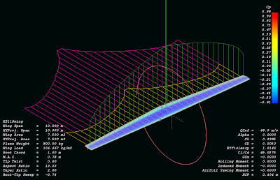
Comparison between NACA and KS118, 2D-simulation
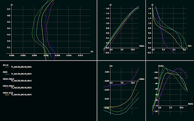
KS118 Cl-alpha polar, including stall region at 1M, comparison with NACA23012 and 23015 included:
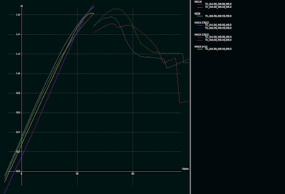

KS118.DAT
Here is a wing simulation with this airfoil:

Comparison between NACA and KS118, 2D-simulation

KS118 Cl-alpha polar, including stall region at 1M, comparison with NACA23012 and 23015 included:


Saturday, October 24, 2009
Airfoil investigation database
Pretty neat airfoil database with search and quick illustration capabilities.
http://www.worldofkrauss.com/
http://www.worldofkrauss.com/
Friday, October 23, 2009
How to simulate a wing with QFLR5 -tutorial
1. Batch simulate airfoil for different Reynolds numbers so that the whole range of the wing is covered (speed you want to simulate + chord length on the root and tip). Fast way to calculate Reynolds numbers and mach numbers for your simulation case is to use this web page:
http://aero.stanford.edu/StdAtm.html
Use the metric values.
2. When you know your Mach number and Reynolds number range (ranging from tip to root), simulate the airfoil of your choice on QFLR5 on that range. Using batch analysis feature.
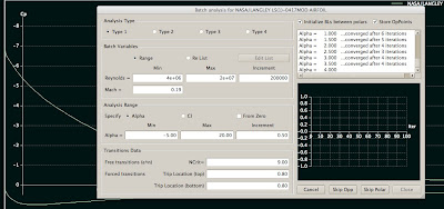
Please note that it can take significant amount of time to batch analysis all the airfoils you want to simulate (e.g. if your wing is going to use more than one airfoil for example, and if you want to compare it to other wings which have different airfoils).
3. Go to Wing and Plane Design. Select from Unit preferences. Replace millimeter units with meter, so you want m/s, m^2, m for length etc.
4. Select Define wing from the menu. A window with a spreadsheet appears.
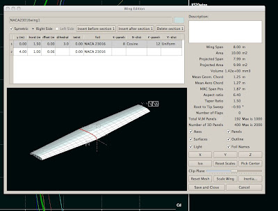
5. Define the wing by entering the y positions (you can define as many as you like). For simple taper it is enough to enter root to y position 0 and then tip to the position where the wing ends. For 12 meters long wing this position is 6 meters (as the plane is quite often symmetric). Select chord length for the root and tip. Select dihedral and twist for the root and tip. Select foil for the root and tip. Select the number of panels you want for the simulation. The more panels, the more accurate. Please note that the dimensions here affect to the Reynolds number, so if your simulation later says it is out of flight envelope, it means that you have not simulated in the Foil direct analysis section the appropriate Reynolds number range, something is missing. Please go back to the web site stated above and check your Reynolds numbers.
6. When you have a wing with desired shape with desired airfoils, click Save and Close from the bottom.
8. Select from Polars menu Define analysis. Select your simulation speed. Please note that this affects your Reynolds number. You need to know at this point your desired speed you want to fly. Select plane weight and moment location on the wing. You can
then select 3D panels. For example I have 150 kt, 800 kg, 0.40 m, 0.00, 0.00.
9. Analysis settings on the right, uncheck sequence if you are interested in one angle of attack only. This most likely is the case if you want to simulate a constant speed (e.g. the 150 kts described above). Then click Analyze and your wing is analyzed for that angle of attack.
Some examples of analyzed wings:
NACA4415:
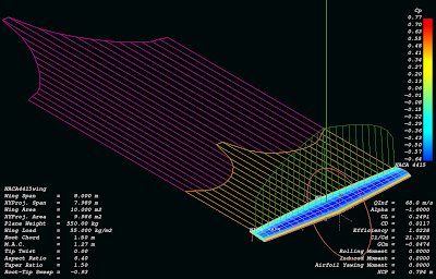
KS20 (same wing):
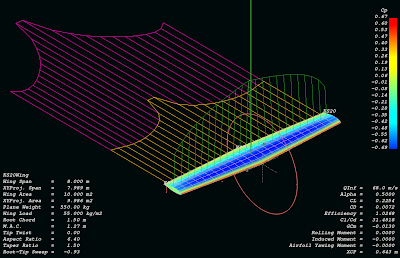
NASA NLF414F (same wing again):
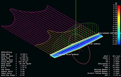
http://aero.stanford.edu/StdAtm.html
Use the metric values.
2. When you know your Mach number and Reynolds number range (ranging from tip to root), simulate the airfoil of your choice on QFLR5 on that range. Using batch analysis feature.

Please note that it can take significant amount of time to batch analysis all the airfoils you want to simulate (e.g. if your wing is going to use more than one airfoil for example, and if you want to compare it to other wings which have different airfoils).
3. Go to Wing and Plane Design. Select from Unit preferences. Replace millimeter units with meter, so you want m/s, m^2, m for length etc.
4. Select Define wing from the menu. A window with a spreadsheet appears.

5. Define the wing by entering the y positions (you can define as many as you like). For simple taper it is enough to enter root to y position 0 and then tip to the position where the wing ends. For 12 meters long wing this position is 6 meters (as the plane is quite often symmetric). Select chord length for the root and tip. Select dihedral and twist for the root and tip. Select foil for the root and tip. Select the number of panels you want for the simulation. The more panels, the more accurate. Please note that the dimensions here affect to the Reynolds number, so if your simulation later says it is out of flight envelope, it means that you have not simulated in the Foil direct analysis section the appropriate Reynolds number range, something is missing. Please go back to the web site stated above and check your Reynolds numbers.
6. When you have a wing with desired shape with desired airfoils, click Save and Close from the bottom.
8. Select from Polars menu Define analysis. Select your simulation speed. Please note that this affects your Reynolds number. You need to know at this point your desired speed you want to fly. Select plane weight and moment location on the wing. You can
then select 3D panels. For example I have 150 kt, 800 kg, 0.40 m, 0.00, 0.00.
9. Analysis settings on the right, uncheck sequence if you are interested in one angle of attack only. This most likely is the case if you want to simulate a constant speed (e.g. the 150 kts described above). Then click Analyze and your wing is analyzed for that angle of attack.
Some examples of analyzed wings:
NACA4415:

KS20 (same wing):

NASA NLF414F (same wing again):

Monday, October 19, 2009
Monday, October 5, 2009
KSNLF51 airfoil - high L/D, high lift, low to medium Re
I created this airfoil one day. I was looking for getting high L/D at low Re. This is pretty nice. I tried simulations as low as Re 100000-300000 (not included in here, you can try by yourself with QFLR5).
Airfoil KSNLF51:

KSNLF51 L/D graph:
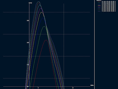
Data file: http://www.katix.org/karoliina/airfoils/KSNLF51.DAT
Polars:
Re 1 million, Mach 0.3
http://www.katix.org/karoliina/airfoils/KSNLF51_T1_Re1.00_M0.30_N9.0.txt
Re 3 millions, Mach 0.3
http://www.katix.org/karoliina/airfoils/KSNLF51_T1_Re3.00_M0.30_N9.0.txt
Re 5 millions, Mach 0.3
http://www.katix.org/karoliina/airfoils/KSNLF51_T1_Re5.00_M0.30_N9.0.txt
License: Creative Commons Share-a-like
Comparison between some airfoils:
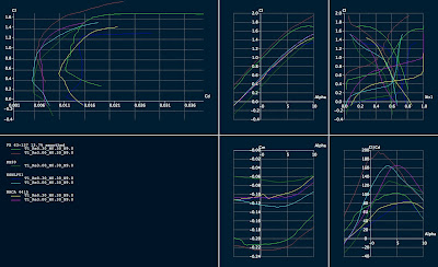
Airfoil KSNLF51:

KSNLF51 L/D graph:

Data file: http://www.katix.org/karoliina/airfoils/KSNLF51.DAT
Polars:
Re 1 million, Mach 0.3
http://www.katix.org/karoliina/airfoils/KSNLF51_T1_Re1.00_M0.30_N9.0.txt
Re 3 millions, Mach 0.3
http://www.katix.org/karoliina/airfoils/KSNLF51_T1_Re3.00_M0.30_N9.0.txt
Re 5 millions, Mach 0.3
http://www.katix.org/karoliina/airfoils/KSNLF51_T1_Re5.00_M0.30_N9.0.txt
License: Creative Commons Share-a-like
Comparison between some airfoils:

Monday, September 21, 2009
Sunday, September 6, 2009
Aerodynamic efficiency index, AEI
I have been trying to come up with my own formula (that differs from the various CAFE formulas to have a weighting that suits me better). I found another interesting comparative formula, the AEI.
AEI = (W0*U0)/hp
where W0 is the gross weight in lbs
where U0 is the free stream velocity in ft/s
where the hp is the horse power required
In other words for Diamond DA40 this is:
W0=1200 kg = 2640 lbs
U0= 214 ft/s (127 kts cruise at 10000 ft)
hp_cruise=90
=>
AEI(Diamond DA40) = (2640*214)/90
AEI(Diamond DA40) = 6277
Unlike the CAFE formula this has no weighting for these parameters.
If I would like to make my formula based on this, I might want to weight the hp a bit more.
That is because the lower the hp figure gets, the better is the fuel economy if everything else remains constant.
Why this index is good? Because it isolates aerodynamics from structural engineering and does not care how much useful load the craft has. It only considers the aerodynamically important point, how much power is required to move the mass forwards and at the same time keep it on air.
AEI = (W0*U0)/hp
where W0 is the gross weight in lbs
where U0 is the free stream velocity in ft/s
where the hp is the horse power required
In other words for Diamond DA40 this is:
W0=1200 kg = 2640 lbs
U0= 214 ft/s (127 kts cruise at 10000 ft)
hp_cruise=90
=>
AEI(Diamond DA40) = (2640*214)/90
AEI(Diamond DA40) = 6277
Unlike the CAFE formula this has no weighting for these parameters.
If I would like to make my formula based on this, I might want to weight the hp a bit more.
That is because the lower the hp figure gets, the better is the fuel economy if everything else remains constant.
Why this index is good? Because it isolates aerodynamics from structural engineering and does not care how much useful load the craft has. It only considers the aerodynamically important point, how much power is required to move the mass forwards and at the same time keep it on air.
Friday, September 4, 2009
AOPA article about Klaus Savier's 100 mpg Vari-Ez
Here is a link to the article by AOPA about Klaus Savier's Vari-Ez.
“For all these guys that think magnetos are so great, I only have one question: Why don’t you put magnetos in your cars?” Read more by clicking the link below:
http://www.aopa.org/aircraft/articles/2008/081230100mpg.html?WT.mc_id=090102epilot&WT.mc_sect=gan
“For all these guys that think magnetos are so great, I only have one question: Why don’t you put magnetos in your cars?” Read more by clicking the link below:
http://www.aopa.org/aircraft/articles/2008/081230100mpg.html?WT.mc_id=090102epilot&WT.mc_sect=gan
Thursday, September 3, 2009
Tuesday, September 1, 2009
TMS turbo installation on Rotax 914
Here is an article about turbo system of the highly modified Rotax:
http://www.designnews.com/article/13660-Turbo_power_reaches_new_heights.php
Interesting web site:
http://www.minijets.org/typo3/index.php
http://www.designnews.com/article/13660-Turbo_power_reaches_new_heights.php
Interesting web site:
http://www.minijets.org/typo3/index.php
Tuesday, August 25, 2009
Tractor vs. pusher
There is lots of strong feelings about tractor vs. pusher propeller configuration but no exact generic answer. Here is one article about the topic. Does not make definitive answer, but gives some background for the topic:
http://www.flyingmag.com/technicalities/1582/pusher-pusher.html
Here is another article:
http://dic.academic.ru/dic.nsf/enwiki/514042
Forum discussion
Another forum discussion
http://www.aiaa.org/content.cfm?pageid=406&gTable=mtgpaper&gID=50663
Tractor (prop forward of laminar flow wing):
http://www.aiaa.org/content.cfm?pageid=406&gTable=Paper&gID=1248
http://www.flyingmag.com/technicalities/1582/pusher-pusher.html
Here is another article:
http://dic.academic.ru/dic.nsf/enwiki/514042
Forum discussion
Another forum discussion
http://www.aiaa.org/content.cfm?pageid=406&gTable=mtgpaper&gID=50663
Tractor (prop forward of laminar flow wing):
http://www.aiaa.org/content.cfm?pageid=406&gTable=Paper&gID=1248
Monday, August 24, 2009
Hypotenuse and catheti and how blending makes wetted area not larger but actually smaller!
Most aircraft have larger than necessary wetted area and not so optimal body shape. One could think without thinking in more detail that wetted area is saved by lofting the plane so that the engine cowling is part of the main fairing and then there is a minimum canopy added on top of that.
However, a little thinking further: which one is the shortest route always, hypotenuse or catheti? Unlike the first thing which comes to mind when looking at planes and saving wetted area, instead of having this complicated shape, actually having more volume and fairing everything in the single form actually produces not only easiest path to the airflow, but also it produces lowest possible wetted area. So making the fuselage larger by removing canopy and putting the cockpit inside the main shape decreases wetted area and drag instead of increasing it. The shallower angle for windows does not decrease the visibility - the visibility can remain still the same. The only problem comes from the optical quality of the windows - as you are looking them from angled direction, you are looking through more plexiglass than you otherwise would and it can degrade the visibility. However - the visibility directly forwards is usually not so good in single engine aircraft which have engine in the front and it is neither better on planes without engine on front since somehow designers seem to not think that people would like to see straight forward very well too. Some twin engine planes have very high panels and poor visibility forwards despite of the fact not having the engine in front would make it possible to make the forward visibility a lot better than that.
So the design on CAD system becomes easy when the shape is not complicated but super simple. And in turn the super simple shape (convex to all directions though, in that sense not so simple, but I mean it is a single loft) has the best drag coefficient and the best wetted area too. At times it feels unbelievable that the solution can be so simple (and I have difficulty to believe it myself when looking e.g. our shared ownership Diamond DA40, it has many shapes, parts and forms), but who says that it has to have so many shapes. Nobody. So it will not have so many different shapes and forms if one shape can do it all. And who says the instrument panel needs to be panel and everything laid out to the panel? Nobody again. A bit more creativity and a lot better forward visibility is achieved despite of not having a bubble canopy and despite of having a pressurized fuselage.
Blending the fuselage to the wings increases frontal area. But who cares about the frontal area. It has very little effect to the drag in airplanes. It is all about wetted area and saving in the wetted area (in addition to maximizing the laminar flow). So blending the wing decreases wetted area - hypotenuse again, it is not a good idea to follow catheti. And the air likes that too - in fuselage wing joint the airflow can not sustain laminar flow. But what if you eliminate the joint and at the same time save in the wetted area. Great stuff.
One could say that it is hard to make a door to a such fuselage. Yes it is hard to make a door. But the solution for the door is to eliminate the door. A hatch that has no hinges and that is larger than the hole is the most light weight door one can imagine. It does not require complicated mechanism to hold it on place and it does not require lots of latches. It holds on place by itself because of the air pressure differential. It can be locked with a lot lesser heavy duty mechanics from inside to the fuselage. And how to ensure the hatch does not ever get out of the hole? That is super easy too: the hole and hatch can be circular and there is no way to put a larger circle out of a smaller circular hole. Not even magicians can do that!
Now then the window problem:
- to glue windows on pressurized fuselage, how to make sure the windows don't rip themselves out - how to glue them on place. Keep it simple and stupid solution: glue them to the inside so that they are larger than the hole in the fuselage. Now what, we have a problem that there is a dent outside of the fuselage on the window area which is really bad for the airflow. No problem again, there can be a simple non-pressurized window that is glued to the outside and faired level with the fuselage around it. It is also a fail-safe: if the windows that are exposed to outside get scratches, no problem, it does not affect the pressurized fuselage - these windows can be replaced fairly easily. And guess what, no bolts are needed, no rivets are needed, very simple.
Then how to get the blended fuselage to work with pressurization. Again super simple: the blend can be fairing on the outside and the pressure vessel can be tubular with completely circular cross section inside.
However, a little thinking further: which one is the shortest route always, hypotenuse or catheti? Unlike the first thing which comes to mind when looking at planes and saving wetted area, instead of having this complicated shape, actually having more volume and fairing everything in the single form actually produces not only easiest path to the airflow, but also it produces lowest possible wetted area. So making the fuselage larger by removing canopy and putting the cockpit inside the main shape decreases wetted area and drag instead of increasing it. The shallower angle for windows does not decrease the visibility - the visibility can remain still the same. The only problem comes from the optical quality of the windows - as you are looking them from angled direction, you are looking through more plexiglass than you otherwise would and it can degrade the visibility. However - the visibility directly forwards is usually not so good in single engine aircraft which have engine in the front and it is neither better on planes without engine on front since somehow designers seem to not think that people would like to see straight forward very well too. Some twin engine planes have very high panels and poor visibility forwards despite of the fact not having the engine in front would make it possible to make the forward visibility a lot better than that.
So the design on CAD system becomes easy when the shape is not complicated but super simple. And in turn the super simple shape (convex to all directions though, in that sense not so simple, but I mean it is a single loft) has the best drag coefficient and the best wetted area too. At times it feels unbelievable that the solution can be so simple (and I have difficulty to believe it myself when looking e.g. our shared ownership Diamond DA40, it has many shapes, parts and forms), but who says that it has to have so many shapes. Nobody. So it will not have so many different shapes and forms if one shape can do it all. And who says the instrument panel needs to be panel and everything laid out to the panel? Nobody again. A bit more creativity and a lot better forward visibility is achieved despite of not having a bubble canopy and despite of having a pressurized fuselage.
Blending the fuselage to the wings increases frontal area. But who cares about the frontal area. It has very little effect to the drag in airplanes. It is all about wetted area and saving in the wetted area (in addition to maximizing the laminar flow). So blending the wing decreases wetted area - hypotenuse again, it is not a good idea to follow catheti. And the air likes that too - in fuselage wing joint the airflow can not sustain laminar flow. But what if you eliminate the joint and at the same time save in the wetted area. Great stuff.
One could say that it is hard to make a door to a such fuselage. Yes it is hard to make a door. But the solution for the door is to eliminate the door. A hatch that has no hinges and that is larger than the hole is the most light weight door one can imagine. It does not require complicated mechanism to hold it on place and it does not require lots of latches. It holds on place by itself because of the air pressure differential. It can be locked with a lot lesser heavy duty mechanics from inside to the fuselage. And how to ensure the hatch does not ever get out of the hole? That is super easy too: the hole and hatch can be circular and there is no way to put a larger circle out of a smaller circular hole. Not even magicians can do that!
Now then the window problem:
- to glue windows on pressurized fuselage, how to make sure the windows don't rip themselves out - how to glue them on place. Keep it simple and stupid solution: glue them to the inside so that they are larger than the hole in the fuselage. Now what, we have a problem that there is a dent outside of the fuselage on the window area which is really bad for the airflow. No problem again, there can be a simple non-pressurized window that is glued to the outside and faired level with the fuselage around it. It is also a fail-safe: if the windows that are exposed to outside get scratches, no problem, it does not affect the pressurized fuselage - these windows can be replaced fairly easily. And guess what, no bolts are needed, no rivets are needed, very simple.
Then how to get the blended fuselage to work with pressurization. Again super simple: the blend can be fairing on the outside and the pressure vessel can be tubular with completely circular cross section inside.
Saturday, August 22, 2009
First atlantic crossing completed
We completed the first atlantic crossing in the N756DS (Diamond DA40) on Wednesday and arrived to Helsinki-Malmi. There will be a presentation about the trip in SIL-luokka Helsinki-Malmi later. I will let you know more about it when I know more details and have prepared the presentation. If you are a reporter in a newspaper or magazine and want to write a story about our not so ordinary adventure, feel free to contact me karoliina dot t dot salminen at gmail dot com.
We received the ferry flight training from Edward Carlson.
We want to do the trip again also, if you are looking for inexpensive ferrying from USA to Finlandm or to any other European country via Denmark/Opmas, I am glad to inform that the Danish VAT will work still to next summer as followings: if you buy aircraft this year before the end of the year and complete all the agreements, according to Opmas, the plane can still benefit from the Danish VAT if it is ferried on the first half of 2010. We would be glad to help for free (no ferry flight fee) at the price of the expenses (gasoline, hotel (we choose cheapest options always), maintenance needed for the plane, airport fees). If you are interested in inexpensive ferry (or should I say delivery) flight, please contact me to the abovementioned address. You can not fly the North Atlantic for first time by yourself, but you need someone that has flown it before to get insurance (which is mandatory for the flight). We have now flown it once and are willing to help people who haven't flown it yet and/or who do not want to fly it by themselves. The summer time is the best time for ferrying an aircraft because of weather. We will spend our summer vacation for flying your plane for free, you can not get better deal from anybody. We agree to fly the following aircraft make and models: Diamond DA40-180/G1000, Diamond DA40XL/G1000, Diamond DA40-CS/G1000, Diamond DA40-180/Avidyne, Cirrus SR20/Avidyne, Cirrus SR22/Avidyne, Cirrus SR22/Garmin Perspective or Diamond or Cirrus with any other comparable glass cockpit avionics - this list is based on our prior flying experience - we have flown Diamonds and Cirruses before. We can consider also other aircraft, but that will rise the expenses a bit since we need to get checked out to these prior flying the trip. I could estimate that most familiar of those would be Columbia 350, Columbia 400, Cessna 350 Corvalis, Cessna 400 Corvalis and these we would be glad to fly providing that we would get proper check-out before starting the trip to feel comfortable enough flying the plane in not so ideal conditions. We may not agree to fly steam-gauge IFR planes and surely will not agree to fly VFR-only equipped planes. Also we will not fly C172, because that is not suitable for the trip. We are not interested in taking unnecessary risks, we want to deliver.
We received the ferry flight training from Edward Carlson.
We want to do the trip again also, if you are looking for inexpensive ferrying from USA to Finlandm or to any other European country via Denmark/Opmas, I am glad to inform that the Danish VAT will work still to next summer as followings: if you buy aircraft this year before the end of the year and complete all the agreements, according to Opmas, the plane can still benefit from the Danish VAT if it is ferried on the first half of 2010. We would be glad to help for free (no ferry flight fee) at the price of the expenses (gasoline, hotel (we choose cheapest options always), maintenance needed for the plane, airport fees). If you are interested in inexpensive ferry (or should I say delivery) flight, please contact me to the abovementioned address. You can not fly the North Atlantic for first time by yourself, but you need someone that has flown it before to get insurance (which is mandatory for the flight). We have now flown it once and are willing to help people who haven't flown it yet and/or who do not want to fly it by themselves. The summer time is the best time for ferrying an aircraft because of weather. We will spend our summer vacation for flying your plane for free, you can not get better deal from anybody. We agree to fly the following aircraft make and models: Diamond DA40-180/G1000, Diamond DA40XL/G1000, Diamond DA40-CS/G1000, Diamond DA40-180/Avidyne, Cirrus SR20/Avidyne, Cirrus SR22/Avidyne, Cirrus SR22/Garmin Perspective or Diamond or Cirrus with any other comparable glass cockpit avionics - this list is based on our prior flying experience - we have flown Diamonds and Cirruses before. We can consider also other aircraft, but that will rise the expenses a bit since we need to get checked out to these prior flying the trip. I could estimate that most familiar of those would be Columbia 350, Columbia 400, Cessna 350 Corvalis, Cessna 400 Corvalis and these we would be glad to fly providing that we would get proper check-out before starting the trip to feel comfortable enough flying the plane in not so ideal conditions. We may not agree to fly steam-gauge IFR planes and surely will not agree to fly VFR-only equipped planes. Also we will not fly C172, because that is not suitable for the trip. We are not interested in taking unnecessary risks, we want to deliver.
Sunday, August 16, 2009
First Northern Atlantic Crossing
I have been recently a bit silent on this blog. The reason have been that I have been too busy and out of Internet most of the time. In other words, I have been flying.
I am typing this from Iceland. Our trip has been so far quite incredible:
1. from Helsinki to Miami with airliner
2. from Miami to Jacksonville with car
3. from Jacksonville to St. Louis with plane, N756DS
4. from St. Louis to Pueblo with N756DS
5. from Pueblo to Palo Alto with N756DS
6. IFR training in San Francisco Bay Area with N756DS
7. from Palo Alto to Sioux Falls with N756DS
8. from Sioux Falls to Oshkosh with N756DS
9. spent couple of days in Oskosh/Airventure 2009. Camp with Cozygirrrls.
10. from Oshkosh to Rhode Island with N756DS
11. from Rhode Island to Wabush (Canada) with N756DS. First Northern Atlantic Crossing in a small airplane was started for us. We are flying with Ed Carlson (he is a ferry flight instructor specialized in Northern Atlantic crossing).
12. from Wabush to Kuujjaq (Canada) with N756DS
13. from Kuujjaq (Canada) to Iqaluit (Canada) with N756DS
14. from Iqaluit (Canada) to Kangerlussuaq (Greenland) with N756DS
15. from Kangerlussuaq (Greenland) to Kulusuk (Greenland) with N756DS
16. from Kulusuk (Greenland) to Reykjavik (Iceland) with N756DS
17. from Reykjavik (Iceland) to EGILSSTADIR with N756DS
We will continue to Faroe Island / Vagar next. After that is either Bergen or Stavanger in Norway.
Kate has been keeping a blog about the adventure here:
http://n756ds.blogspot.com
I am typing this from Iceland. Our trip has been so far quite incredible:
1. from Helsinki to Miami with airliner
2. from Miami to Jacksonville with car
3. from Jacksonville to St. Louis with plane, N756DS
4. from St. Louis to Pueblo with N756DS
5. from Pueblo to Palo Alto with N756DS
6. IFR training in San Francisco Bay Area with N756DS
7. from Palo Alto to Sioux Falls with N756DS
8. from Sioux Falls to Oshkosh with N756DS
9. spent couple of days in Oskosh/Airventure 2009. Camp with Cozygirrrls.
10. from Oshkosh to Rhode Island with N756DS
11. from Rhode Island to Wabush (Canada) with N756DS. First Northern Atlantic Crossing in a small airplane was started for us. We are flying with Ed Carlson (he is a ferry flight instructor specialized in Northern Atlantic crossing).
12. from Wabush to Kuujjaq (Canada) with N756DS
13. from Kuujjaq (Canada) to Iqaluit (Canada) with N756DS
14. from Iqaluit (Canada) to Kangerlussuaq (Greenland) with N756DS
15. from Kangerlussuaq (Greenland) to Kulusuk (Greenland) with N756DS
16. from Kulusuk (Greenland) to Reykjavik (Iceland) with N756DS
17. from Reykjavik (Iceland) to EGILSSTADIR with N756DS
We will continue to Faroe Island / Vagar next. After that is either Bergen or Stavanger in Norway.
Kate has been keeping a blog about the adventure here:
http://n756ds.blogspot.com
Sunday, June 28, 2009
Sunday, June 7, 2009
LINK: How to design blended wing body RC airplane
http://rcairplanedesign.googlepages.com/Design-BWB-Blended-Wing-Body-RCplane.htm
The mentioned AVL can be found from the following address:
http://web.mit.edu/drela/Public/web/avl/
The mentioned AVL can be found from the following address:
http://web.mit.edu/drela/Public/web/avl/
Thursday, June 4, 2009
Sunday, May 31, 2009
Misc tech paper etc. link collection
I created a wiki page to katix gforge for link collection.
I hope you like it. It is not sorted in any sense, but it contains lots of interesting links. A friend of mine has been sending these to me a quite long time and I thought that I could share the collection with you.
http://gforge.katix.org/gf/project/twinzygger/wiki/?pagename=MiscTechPapers
I hope you like it. It is not sorted in any sense, but it contains lots of interesting links. A friend of mine has been sending these to me a quite long time and I thought that I could share the collection with you.
http://gforge.katix.org/gf/project/twinzygger/wiki/?pagename=MiscTechPapers
Wednesday, May 27, 2009
Tailed blended wing body with laminar flow body and Goldschmied suction and pressure thrust
New idea:
- A body that comprises of a laminar body and wing blended together
- There is a V-tail in a blended boom
- Rear of the center section has suction slot on top side
- The boom contains a electric fan that is used for suction and additional thrust
- There are two turbocharged Rotax 912UL engines in the wings which are hidden in blended pods that continue the airfoil shape of the wing without interruption
- Both engines turn additional turbochargers which drive generators which generate electricity for the rear fan of the aircraft
Items that need to be studied:
- does pressure thrust work with this kind of shape, or does it require axisymmetric body?
- compare the drag of minimum axisymmetric body with non-blended wings to a blended wing body which has larger cross sectional area, but potentially lower wetted area.
- wing incidence relative to the center section - center section has a lower aspect ratio than the wings and what it requires to achieve optimal lift distribution in this combined case
- the achievable gain from the lack of interference drag or very small interference drag
- optimal wing loading for a combined blended wing body compared to a pod+boom+wings solution
- shark fin shape on the outer wing sections, the gain and the issues
- A body that comprises of a laminar body and wing blended together
- There is a V-tail in a blended boom
- Rear of the center section has suction slot on top side
- The boom contains a electric fan that is used for suction and additional thrust
- There are two turbocharged Rotax 912UL engines in the wings which are hidden in blended pods that continue the airfoil shape of the wing without interruption
- Both engines turn additional turbochargers which drive generators which generate electricity for the rear fan of the aircraft
Items that need to be studied:
- does pressure thrust work with this kind of shape, or does it require axisymmetric body?
- compare the drag of minimum axisymmetric body with non-blended wings to a blended wing body which has larger cross sectional area, but potentially lower wetted area.
- wing incidence relative to the center section - center section has a lower aspect ratio than the wings and what it requires to achieve optimal lift distribution in this combined case
- the achievable gain from the lack of interference drag or very small interference drag
- optimal wing loading for a combined blended wing body compared to a pod+boom+wings solution
- shark fin shape on the outer wing sections, the gain and the issues
Saturday, May 23, 2009
Thursday, May 21, 2009
High transition length NLF body
I was looking Parson's high transition length body in a book and thought that maybe if I modify my body shape also so that the nose becomes sharper. By sacrificing some interior space, the flow acceleration can be kept for high transition length according the book I was reading this. My modified body looks like this.

Despite the QFLR5 algorithm is not maybe designed for simulating NLF bodies (it is designed for simulating wings), the pressure distribution looks like the same as the wind tunnel data for the Parson's body which makes me think that it might not be that much wrong.

Despite the QFLR5 algorithm is not maybe designed for simulating NLF bodies (it is designed for simulating wings), the pressure distribution looks like the same as the wind tunnel data for the Parson's body which makes me think that it might not be that much wrong.
Wednesday, May 20, 2009
Wolfram
Ever wanted a Star Trek's computer? It is here today:
http://www.wolframalpha.com/
For starters, try out for example: integrate x+y^2
This service is superb.
http://www.wolframalpha.com/
For starters, try out for example: integrate x+y^2
This service is superb.
Thursday, May 14, 2009
Random thinking about the feasibility of fabrication of a partial pressure suit
I have been thinking this topic for quite a long time and my old conclusion was that it is not feasible. However, there is very little information about pressure suits out there, but looking at the very little there is about the old Mercury suits etc., I have got indications that actually fabrication of a partial pressure suit might be feasible. Buying one might not be feasible because of lack of availability and insane pricing.
I would like to learn more about the topic, but in the Internet at least, there is very little or nothing. If someone has some insight, please leave some comments.
I would like to learn more about the topic, but in the Internet at least, there is very little or nothing. If someone has some insight, please leave some comments.
Wednesday, May 13, 2009
Fuselage drag reduction principle

A major portion of aircraft drag (in addition to the wing) is generated by the fuselage. The poor aircraft has to drag the draggy fuselage forwards. It is justified to target for reducing the fuselage drag in addition to the drag of the wings to achieve high L/D ratio and thus high efficiency and exceptional miles per gallon figure.
The idea comprises of the following claims:
- a laminar body with optimal fineness ratio for minimum drag
- a tail boom behind the optimal fineness ratio laminar pod
- electric motor (or couple of electric motors in cascade) turn
one or many ducted fans that are in cascade inside the rear of the fuselage.
The fan(s) take their air intake from the boundary layer of the fuselage.
- the fans are driven with batteries on takeoff.
- the fans are driven in cruise with electricity generated from the exhaust gas of the two gasoline engines which are mounted in wings.
- there is an additional turbine mounted in the exhaust that turns a generator rather than compressing air for the gasoline engine.
- the exhaust for the air is either in the tail boom prior to the tail or after the tail, whichever is found to provide best results.
- the fans provide suction for the fuselage boundary layer and also additional thrust for the aircraft. This configuration however, does not cause additional drag for the aircraft but reduces it.
- additional generators can be mounted to wing tip vortices so that the wing tip vortex turns the turbine blades and thus generates electricity for the fans located in the rear of the fuselage.
- the generators, battery charging and fans are computer controlled.
- the fans utilize all power that can be drawn from the exhaust gas and the wing tip turbines and thus runs at full power available to it continuously. On takeoff batteries are used to ensure high centerline thrust for the hypothetical situation where one of the gasoline engines would fail.
Goldschmied papers online
I found these some time ago, but now got reminded about it also on one comment to a previous post. Therefore I decided to open a new topic for it:
Goldschmied drag reduction tech papers:
http://cafefoundation.org/v2/pav_enablingtech_dragreduction.php
Interesting reading for anyone interested in achieving major breakthroughs in the fuselage drag.
Goldschmied drag reduction tech papers:
http://cafefoundation.org/v2/pav_enablingtech_dragreduction.php
Interesting reading for anyone interested in achieving major breakthroughs in the fuselage drag.
Thursday, May 7, 2009


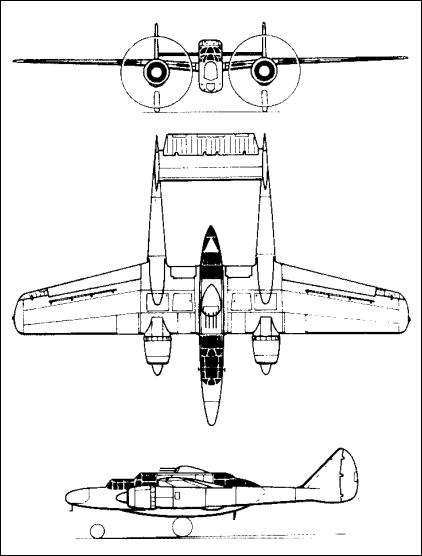
Subscribe to:
Posts (Atom)